MAP sensor – How MAP sensor work & failed?
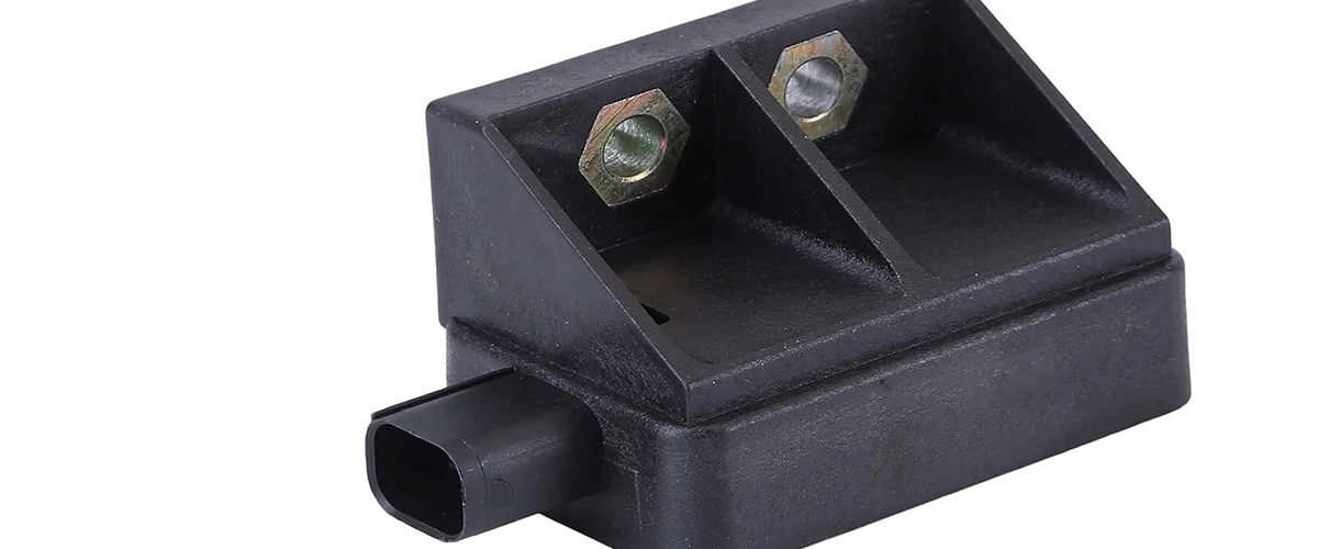
Commonly found in fuel-injected engines, the manifold absolute pressure (MAP) sensor is one of the sensors used by the engine control module (ECM) to calculate fuel injection to achieve the optimal air-fuel ratio by continuously monitoring intake manifold pressure information. A mass air flow (MAF) sensor is more commonly used instead of a MAP sensor, but turbocharged engines typically use both a MAP and MAF sensor. The MAP sensor also helps the ECM determine when ignition should occur under various engine load conditions.
Regardless of which sensor your engine uses, the ECM cannot optimize fuel injection without accurate air mass data from a working sensor. And at the very least, a poor air-fuel ratio will cause performance problems and premature engine wear. MAP sensor failure can be difficult to diagnose, but with the help of Delphi Technologies, we can explain what’s causing it, what to look for, and how to replace it when it fails.
How MAP sensor work?
The MAP sensor is usually located on the intake manifold, either next to or on top of the throttle body. (A forced induction engine has a MAP sensor in the intake before the turbo) Inside the MAP sensor is a sealed chamber that has either a vacuum or a controlled pressure that is calibrated for the engine. A flexible silicon wafer (called a chip) is shared between the sensor vacuum and the vacuum inlet manifold, with current passing through it.
When the key is on (before starting the engine) there is no vacuum installed on the MAP sensor, it changes from a signal to the ECM to a useful barometric pressure sensor for determining air density. When the engine is started, the intake manifold pressure decreases, creating a vacuum that is applied to the MAP sensor. When you press the gas pedal, the intake manifold pressure increases, resulting in less vacuum. The pressure differences bend the chip upward into the sealed chamber, causing a change in voltage resistance, which in turn tells the ECU to inject more fuel into the engine. When the accelerator pedal is released, the intake manifold pressure decreases, bending the clip back to idle.
The ECU combines pressure readings from the MAP sensor with data from the IAT (Intake Air Temperature), ECT (Engine Coolant Temperature) sensor, baro reading, and engine speed (RPM) to calculate air density and accurately determine engine air mass flow rate for optimal air-to-fuel ratio.
Why MAP sensor failed?
Like most electrical sensors, MAP sensors are sensitive to contamination. If the map sensor uses a hose, the hose may become clogged or leaky and unable to read pressure changes. In some cases, extreme vibrations from driving can loosen its connections and cause external damage. Electrical connections can also melt or crack due to overheating due to proximity to the engine. In either of these scenarios, the MAP sensor will need to be replaced.
Common MAP sensor fault codes
Here is a list of codes related to the MAP sensor to look for if your check engine light is on:
- P0068: MAP/MAF – Throttle Position Correlation
- P0069: Manifold Absolute Pressure – Barometric Pressure Correlation
- P0105: MAP Circuit Malfunction
- P0106: MAP / Barometric Pressure Circuit Range / Performance Problem
- P0107: Manifold Absolute Pressure / Barometric Pressure Circuit Low Input
- P0108: MAP Pressure Circuit High Input
- P0109: MAP / Baro Pressure Circuit Intermittent
- P1106: MAP/BARO Pressure Circuit Range/Performance Problem
- P1107: Barometric Pressure Sensor Circuit Low Voltage
Note: Sometimes different sensors or other defective parts can cause these codes to set. Even if your engine exhibits the symptoms listed above and triggers one or more of the listed OBD-II codes, it is recommended that you test the MAP sensor to confirm its fault.
What to pay attention to in the case of a failed MAP sensor?
A faulty MAP sensor affects the engine’s air-fuel ratio. If the ratio is incorrect, the engine will misfire at the wrong time during the combustion cycle. If severe detonation continues for an extended period of time, internal engine components (such as pistons, connecting rods, connecting rods) will be damaged and eventually lead to catastrophic failure. Look for these warning signs:
- Rich Air-Fuel Ratio: Look for rough idle, poor fuel economy, slow acceleration, and a strong gasoline smell (especially when idling)
- Air/Fuel Ratio: Look for surging, stalling, lack of power, acceleration hesitation, intake backlash, and overheating
- Explosion and shooting
- Failed release attempt
- Check engine lights
A rebuilt engine is much more difficult than replacing a sensor, so if your engine is experiencing any of the above symptoms, consider troubleshooting the MAP sensor.
Troubleshooting a MAP sensor
Before testing, check the physical appearance of the MAP sensor. Start by checking the fitting and wiring for damage, such as melted or cracked wires, and make sure there are no loose connections. Disconnect the sensor and check the buttons; they must be straight and clean with no signs of corrosion or bending. Then check (if applicable) the hose connecting the sensor to the intake manifold for signs of damage and that the hose has a tight connection to the sensor. Finally, look inside the hose to make sure the hose is not contaminated.
If everything passes physical inspection, you can test the MAP sensor using a digital multimeter set to 20V and a vacuum pump.
- With the battery on and the engine off, connect the ground of the multimeter to the negative battery terminal and run a quick plausibility test checking the battery voltage. It should be around 12.6 volts.
- Refer to the manufacturer’s service manual for signal, ground, and 5-volt reference wire identification and return probe.
- Turn the ignition switch on without starting the engine. A multimeter should (typically) read between 4.5V and 5V for the 5V reference lead, a steady 0V for the ground lead, and between 0.5V and 1.5V for the signal lead in non-turbo applications, and between 2.0V and 3.0V for turbo in applications. See OEM Factory Services information for exact specifications for your vehicle.
- Start the engine with the signal wire. The multimeter should read 0.5-1.5V at sea level on non-turbocharged vehicles and 2.0-2.5V on turbocharged models.
- Turn off the engine, but leave the ignition on.
- Connect the MAP sensor under the air cleaner only from the intake port.
- Connect the hand vacuum pump and note the voltage on the signal wire.
- Increase the sensor vacuum using a vacuum pump.
- The voltage should drop steadily as the vacuum increases.
If the voltage is significantly different in both tests or the voltage change is incomplete, the MAP sensor is faulty and needs to be replaced.
How to replace a faulty MAP sensor
Replacing a bad MAP sensor varies by vehicle, so consult the manufacturer’s service manual for specific instructions. Once the faulty sensor is removed, it’s a simple matter of installing the new part.
- Place the MAP sensor next to the intake manifold or on the throttle body or on top of the intake manifold.
- Remove the screws or bolts that hold the sensor in place.
- Disconnect the electrical plug. Note: Do not force removal as the connector may contain a locking tab that may need to be removed before the connector can be removed from the sensor.
- If necessary, remove the vacuum hose from the sensor. Note: When changing the sensor, it is recommended to replace the vacuum hose with a new hose.
- Compare new and old sensors.
- Reconnect the vacuum hose if necessary.
- Reconnect the electrical connector of the sensor.
- Reinstall the screws or bolts that hold the sensor in place.
- Check all connections to make sure everything is secure.
Note: Depending on the vehicle and DTC determination, a diagnostic tool may be required to reset the check engine lights.
Get Full Support
MOOCAR — as a leading exporter, we are continually developing breakthrough sensing and actuating solutions to help optimize emissions control, fuel economy, and drivability. In addition to the above parts, we offer full support of data, market information.

