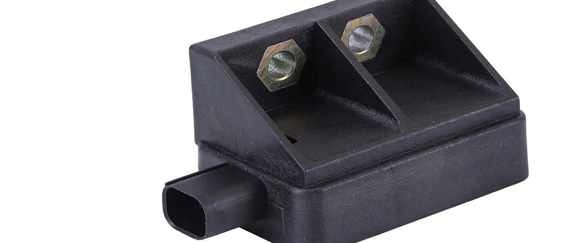
Crankshaft Position Sensor – How it works & failed?
The crankshaft position sensor (CKP sensor or CPS) is one of several sensors that keep your engine running smoothly. It measures the position of the crankshaft (in which case it is sometimes called the Crankshaft Angle Sensor, or CAS), as well as the rotational speed of the crankshaft (in which case it is sometimes called the engine speed sensor, ESS, or the RPM sensor). The paint shaft position sensor transmits this information to the vehicle’s on-board computer, the engine control unit (ECU). The ECU uses this information along with inputs from other sensors to control systems such as ignition timing and fuel injection. This keeps all engine parts well timed and working together. The crankshaft position sensor is essential to a smooth-operating engine.
How crankshaft position sensor works?
There are different settings for crankshaft position sensors, but they tend to work on the principles of magnetism. Many crankshaft position sensors are electronic sensors known as Hall effect sensors. A Hall effect sensor produces electricity when exposed to a magnetic field. In the crankshaft position sensor, the magnetic field is damaged by a gear that rotates with the crankshaft. This produces a pattern of Hall sensor on and off switches that the ECU can interpret as crankshaft speed. The faster the sensor turns on and off, the faster the crankshaft rotates.
Although these Hall effect sensors provide a digital signal, some crankshaft position sensors provide an analog signal. They still work on magnetism. The sensor produces an electrical voltage based on fluctuations in the magnetic field. Fluctuations are caused by the movement of metal parts in the crankshaft. Faster spin means more swing and more tension. The ECU can convert this voltage into crankshaft speed.
In either case, the timing elements, calipers, or teeth on the wheel must be evenly spaced to give an accurate speed measurement. There is usually a gap that fits when one piston is top dead center. This difference allows the sensor, in addition to the speed, to determine where the crankshaft is during rotation.
Why crankshaft position sensor failed?
The crankshaft position sensor is a precision instrument, so it needs to be running in tip-top shape to give an accurate reading. Without accurate readings from the crankshaft sensor, the engine may exhibit all sorts of different problems.
Causes of failure can be:
- Internal short circuits
- Breaks in wiring
- Wiring short circuit
- Mechanical damage to the encoder wheel
- Soiling caused by metal abrasion
- Scratches on the magnetic surface of the sensor
- Foreign material on the magnetic surface of the sensor
- Exposure to significant high heat
Common crankshaft position sensor fault codes
- P0016 Crankshaft Position Camshaft Position Correlation (Bank 1 Sensor A)
- P0017 Crankshaft Position Camshaft Position Correlation (Bank 1 Sensor B)
- P0018 Crankshaft Position Camshaft Position Correlation (Bank 2 Sensor A)
- P0019 Crankshaft Position Camshaft Position Correlation (Bank 2 Sensor B)
- P0335 Crankshaft Position Sensor A Circuit Malfunction
- P0336 Crankshaft Position Sensor A Circuit Range/Performance
- P0337 Crankshaft Position Sensor A Circuit Low Input
- P0338 Crankshaft Position Sensor A Circuit High Input
- P0339 Crankshaft Position Sensor A Circuit Intermittent
- P0340 Camshaft Position Sensor Circuit Malfunction
- P0341 Camshaft Position Sensor Circuit Range/Performance
- P0342 Camshaft Position Sensor Circuit Low Input
- P0343 Camshaft Position Sensor Circuit High Input
- P0344 Camshaft Position Sensor Circuit Intermittent
Symptoms of crankshaft position sensor malfunction
There are a number of reasons why a crankshaft position sensor can fail, and a number of symptoms associated with that failure. Problems with the crankshaft position sensor will often present as problems with engine timing. If you think your sensor has failed, here are some common symptoms of a bad crankshaft sensor that can help you in determining whether or not it has failed.
- Acceleration problems
As engine speed increases, spark timing and fuel injection must be adjusted. Without accurate crankshaft sensor input, the engine control unit (ECU) cannot make these adjustments as well as it should. This can cause slow or uneven acceleration. - Reduced gas mileage
Without accurate timing data, fuel injection will not be as efficient as it should be. This means that the engine has to use more gas and the morning drive uses more fuel than usual. - Engine misfires
Lack of proper spark timing can cause a different problem: one or more cylinders can fail. This means that burning can be disturbing. You will feel and maybe hear it as a short stutter in the engine. - Rough idling
You may feel the engine running rough or vibrating when idling, such as when sitting at a red light. This is similar to the above in that it is caused by bad spark timing. - Engine stalls
As seen with a rough idle, crankshaft position sensor problems are sometimes worse at low RPMs. Sometimes the engine can stall even at low speeds if the fuel injectors are not giving it the fuel it needs. - Hard starting or no starting
Starting an engine can be difficult without the proper fuel or proper timing. If the crankshaft sensor has completely failed and is not sending a signal to the ECU, then the computer is not sending fuel to the injectors. This will not allow you to start the car. - Check engine light on
The crankshaft position sensor can cause the check engine light on the dash to come on. A code between P0335 and P0338 will be displayed using the diagnostic scan tool. The check engine light does not always work, so you may experience some of the above symptoms for a while before you notice the warning light.
Types of crankshaft position sensor
Basically, most vehicles on the road today use one of two types of CKP sensors.
Inductive (magnetic) CKP sensor:
- May have one or two wires
- Mounts in front of a rotor or reluctor wheel
- Produces its own AC voltage signal
Hall-effect CKP sensor:
- May have three or four wires
- Mounts in front of a rotor or reluctor wheel
- Generates a digital (square wave) signal
- Requires an outside power source and a ground to produce the signal
Troubleshooting a crankshaft position sensor
Many problems with the CKP sensor can be located in the wiring harness or the sensor’s connector. So make sure to carefully check them before starting to troubleshoot the sensor itself.
Checking the Wiring and Sensor
- Check the wires for damage.
- Check the wiring.
- Check the mounting bolts of the sensors.
- Check the electrical plug for damage.
- Check the sensor itself for signs of damage.
- If necessary, check the air gap between the tip of the sensor and the rotor. Consult your vehicle’s repair manual for specifications.
- Remove the sensor and check for metal chips or filters stuck to the magnetic end of the sensor.
- Check the sensor reflector wheel for damage.
Testing an Inductive Type CKP Sensor
The following instructions provide an example of testing an inductive type CKP sensor.
Note that some manufacturers provide a shield along the sensor wiring under the insulation. This prevents electrical interference. And the harness connector can have a third wire.
- Remove the CKP sensor electrical connector.
- Set the digital multimeter to the DC voltage scale using the low range.
- Turn the ignition key to the on position, but do not start the engine.
- Touch the DMM’s black lead to ground. It can be a clean surface on the motor, a metal mount or the negative (-) post of the battery.
- Touch the red wire of the DMM to each of the sensor wires you just disconnected. One of the wires should produce about 1.5 volts; Otherwise, the sensor will not receive a reference voltage and must be fixed.
- Prevent the engine from starting
- Set your digital voltmeter to the low range on the AC voltage scale.
- Connect the meter wires to the sensor surfaces. Keep the meter leads away from moving parts of the engine during the test.
- Let the assistant start the engine for a few seconds while you watch the odometer reading.
- The sensor should give a voltage pulse signal. If you do not see voltage pulses, replace the sensor. If the multimeter can measure frequency (Hz), you can use this setting in the same way you check an AC signal. Compare your results with the manufacturer’s specifications. Consult your vehicle’s repair manual.
Testing a Hall Effect Type CKP Sensor
- Remove the fuel pump fuse or relay to prevent the engine from starting during the test.
- Remove the CKP sensor electrical connector.
- Set your DMM to volts DC and range 20V.
- Touch the black wire of the DMM to the black wire of the strap connector.
- Touch the red lead of the DMM to the red (power) lead of the harness connector.
- Turn the ignition key to the on position.
- Your meter should read between 5 and 13 volts. Consult your vehicle’s repair manual for the reference voltage value for your specific model. If the reference voltage is lower than expected or zero, check the wire and connector for damage or a loose terminal. If necessary, check your car’s computer.
- Turn the ignition off and reconnect the CKP sensor to the harness connector.
- Set the DMM to the low DC voltage setting so you can read millivolts.
- Touch the DMM black lead to battery negative.
- Then, using the meter’s red lead, test back to the black ground wire at the harness connector or CKP sensor.
- Ask the assistant to start the engine for a few seconds. Your DMM should register about 200mv to 300mv.
- Now touch the red wire from your DMM to the green (signal) wire on the harness connector or CKP sensor.
- Start the engine for a few seconds. The meter should register about 300 mv. This is the average voltage value of the signal produced by the CKP sensor.
How to replace a faulty crankshaft position sensor
In general, replacing the CKP sensor is a very simple operation. Some models require you to remove one or more components to access the sensor. See your vehicle’s service manual.
- Make sure the engine is cool and the ignition switch is in the off position.
- Disconnect the negative (black) terminal of the battery.
- On some models, it may be necessary to lift the front of the vehicle and attach it to the socket to access the sensor.
- Remove the CKP sensor electrical connector.
- Unscrew the mounting bolts.
- Remove the sensor from the engine.
- Match the old sensor with the new sensor.
- If the sensor has an O-ring, apply a light coat of oil to the O-ring before installing the sensor. This helps with proper sensor installation, helps the sensor generate the
- correct signal, and prevents oil leaks.
- Install the new sensor and tighten the mounting bolts.
- Connect the electrical connector of the sensor.
- Connect the negative pole to the battery.
Get Full Support
MOOCAR — as a leading exporter, we are continually developing breakthrough sensing and actuating solutions to help optimize emissions control, fuel economy, and drivability. In addition to the above parts, we offer full support of data, market information.

