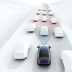
The true test of a steering angle sensor isn’t just how accurately it reads rotation—it’s how safely and reliably it delivers that signal under real-world automotive conditions. We consider the internal architecture, redundancy strategy, and interface selection to be just as important as performance specs. In this article, we’ll explore how steering angle sensors are structured for long-term durability and safety compliance, with a focus on signal interfaces and system integration.
Internal Architecture: A Dual-Channel Core
Most modern steering angle sensors employ a redundant dual-sensing architecture, typically using two Hall-effect sensor chips positioned 180° apart on the rotating shaft or magnet wheel.
Key reasons for redundancy:
- Fulfill ISO 26262 functional safety requirements (commonly ASIL-B or ASIL-C)
- Provide cross-checking for fault detection (e.g., stuck-at, drift, or dropout)
- Enable safe fallback modes in case of single-channel failure
In production, each sensing channel is tested independently, and the ECU constantly monitors for angle mismatch beyond an allowed deviation (e.g., 3°).
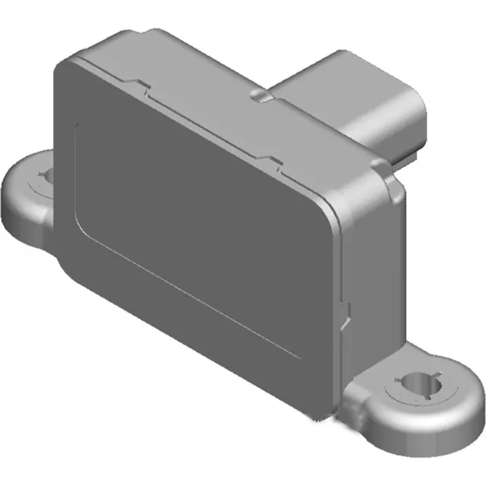
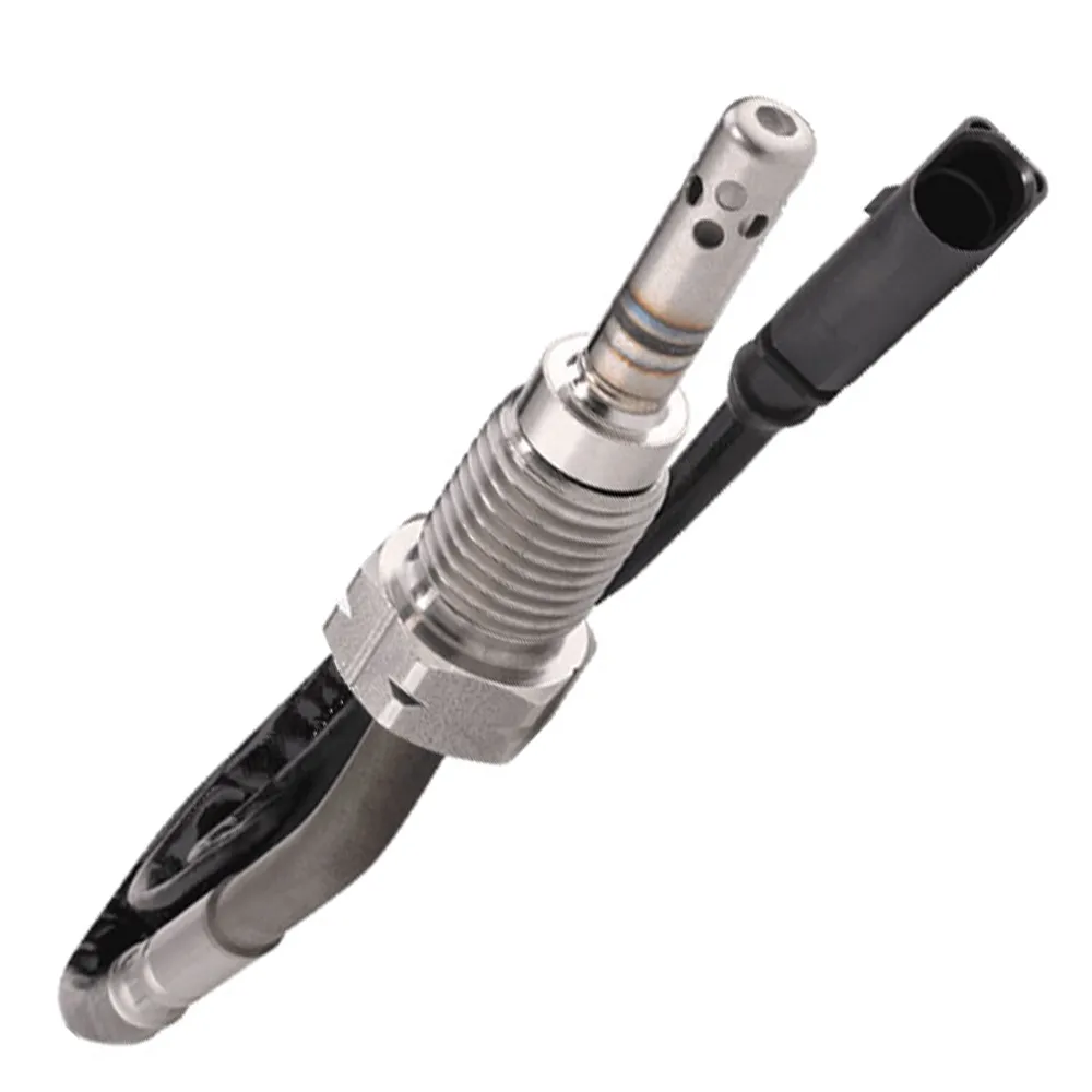
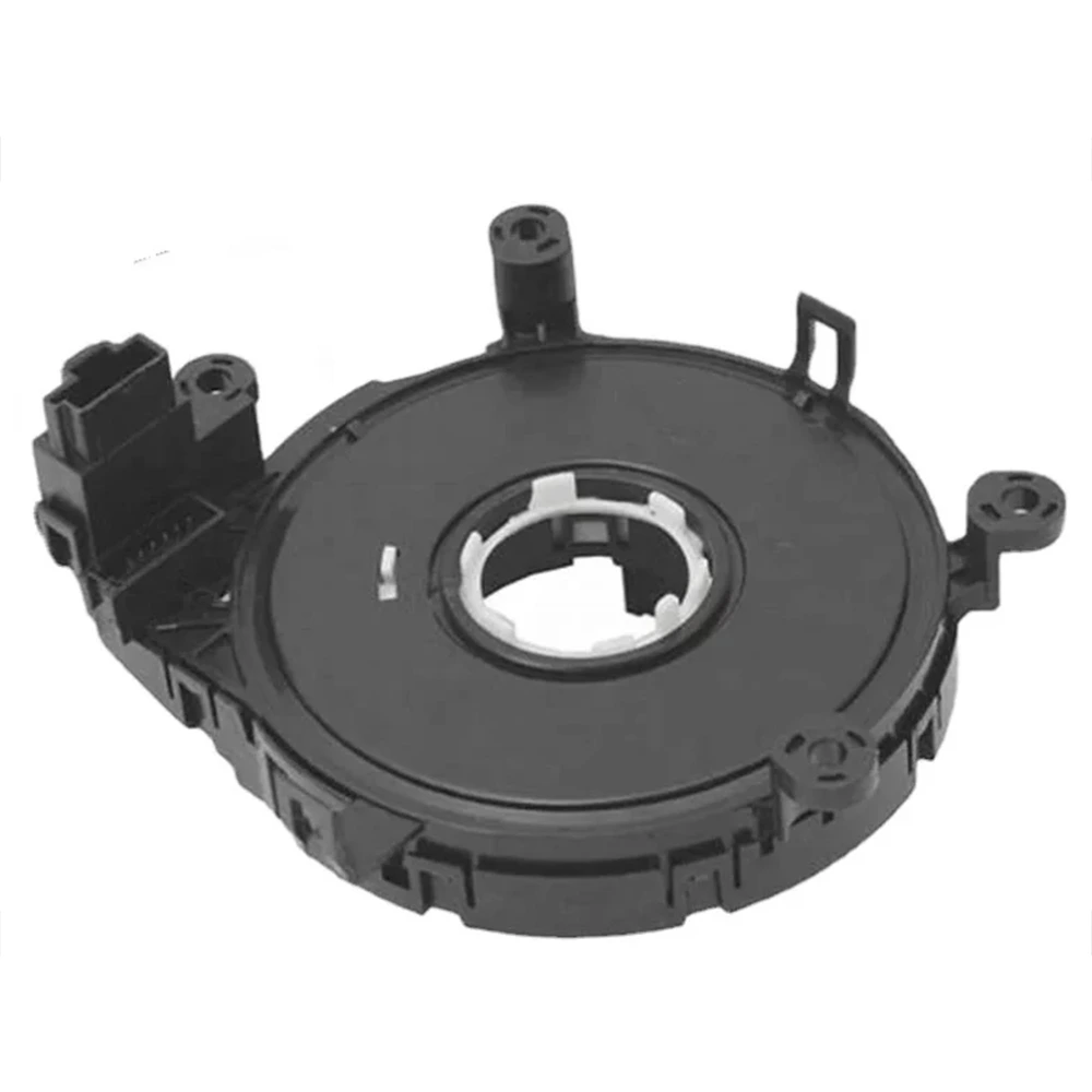
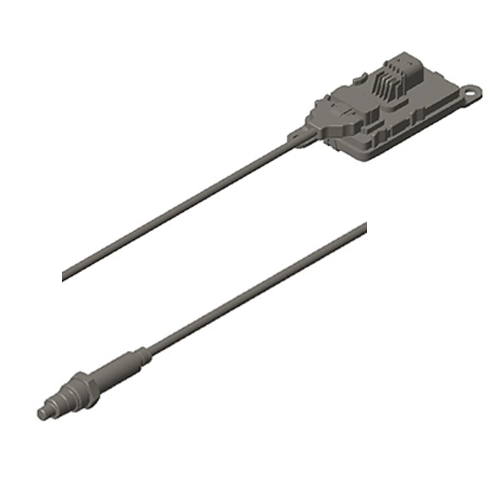
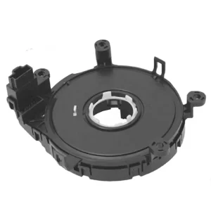
Mechanical Design: Rotational Assembly and Sealing
Sensor assemblies typically consist of:
- A multi-pole magnet ring or magnetized rotor
- One or two Hall-effect ICs
- A rigid PCB with redundant signal lines
- A sealed housing rated up to IP67/IP6K9K, especially for underhood installations
For angular measurements beyond 360° (e.g., ±720°), mechanical designs may include gear-driven rotary encoders or multi-turn tracking algorithms.
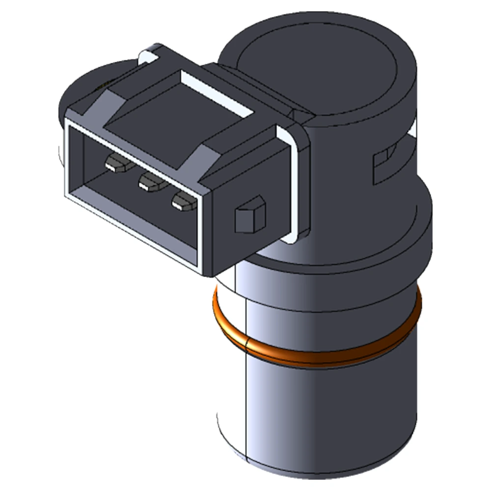
Signal Interfaces: From Analog to CAN and SENT
The signal output method has a direct impact on how the sensor integrates with other vehicle systems. Common interfaces include:
| Interface | Typical Use Case | Pros | Cons |
|---|---|---|---|
| Analog Voltage | Legacy or low-cost systems | Simple | Susceptible to EMI |
| PWM | Simple digital integration | Low-pin-count | Resolution limited by frequency |
| SENT | Entry-level digital, cost-effective | CRC-checked, fast | Needs decoding IC |
| SPI | Close-range, high-speed comm | Accurate | Requires shielded wiring |
| CAN | Advanced ADAS, EPS | Robust, standardized | Higher implementation cost |
Our team usually recommends SENT or CAN for applications where safety, speed, and fault tolerance are priorities.
Functional Safety Design: ISO 26262 Compliance
A critical part of modern sensor architecture is functional safety. Manufacturers are now expected to design in compliance with:
- ISO 26262 (Road Vehicles – Functional Safety)
- Diagnostic coverage (e.g., internal CRC, self-checks, power-on diagnostics)
- Dual-redundant signal paths and watchdog timers
- Design Failure Mode and Effects Analysis (DFMEA) procedures
Safety features built into the sensor firmware may include:
- Clamping outputs to fixed voltages under fault
- Signal de-correlation: Both channels send different waveforms that the ECU interprets
- Zero-point verification post ignition
Electrical and EMI Design Considerations
Steering angle sensors operate in environments with electrical noise from ignition coils, inverters, and LIN/CAN buses. Key protection design features include:
- TVS diodes for ESD protection
- Reverse polarity protection at the power input
- Shielded cables and twisted pair for CAN/SENT
- Robust ground isolation and filtering at the PCB level
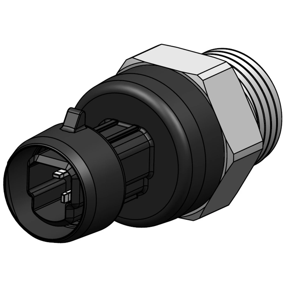
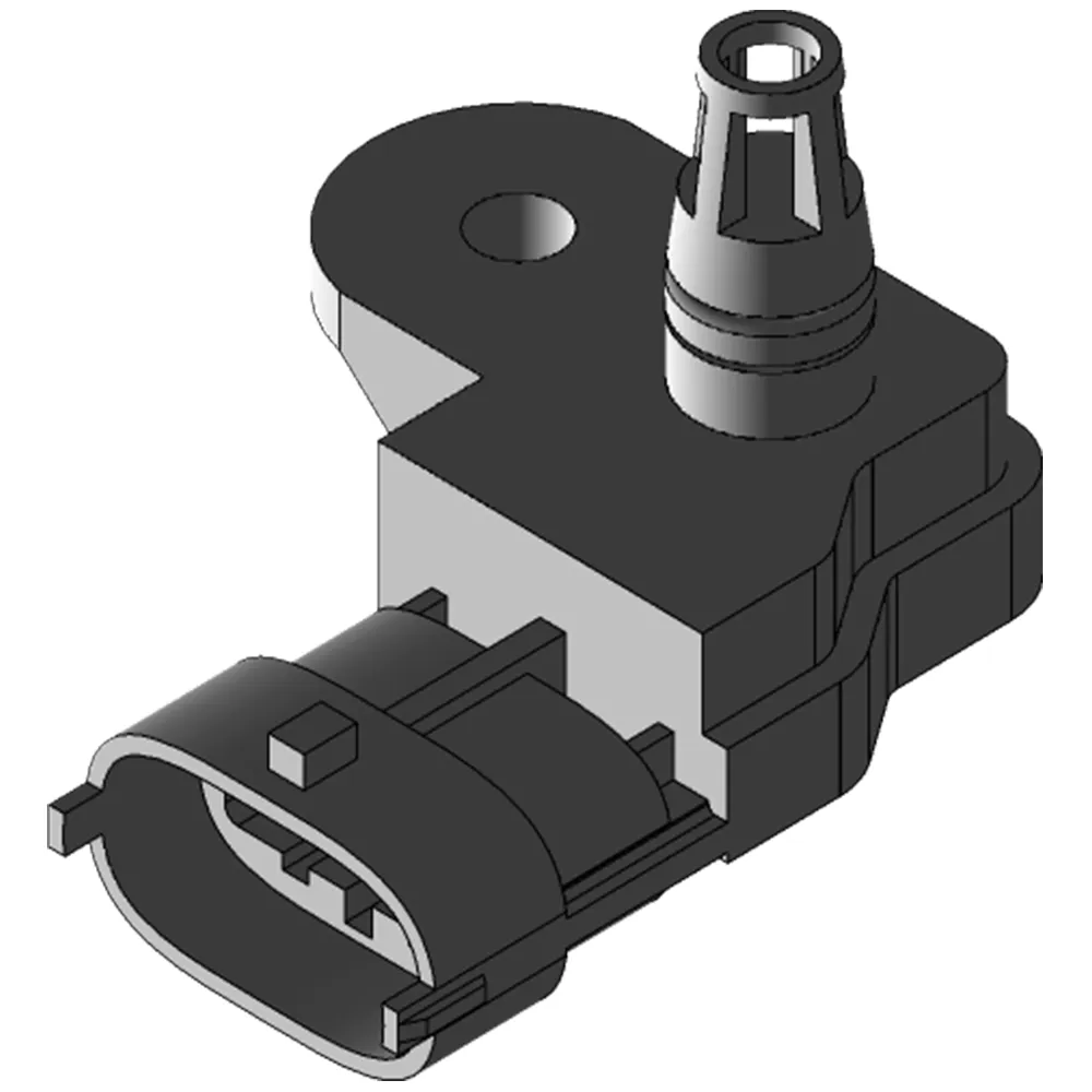
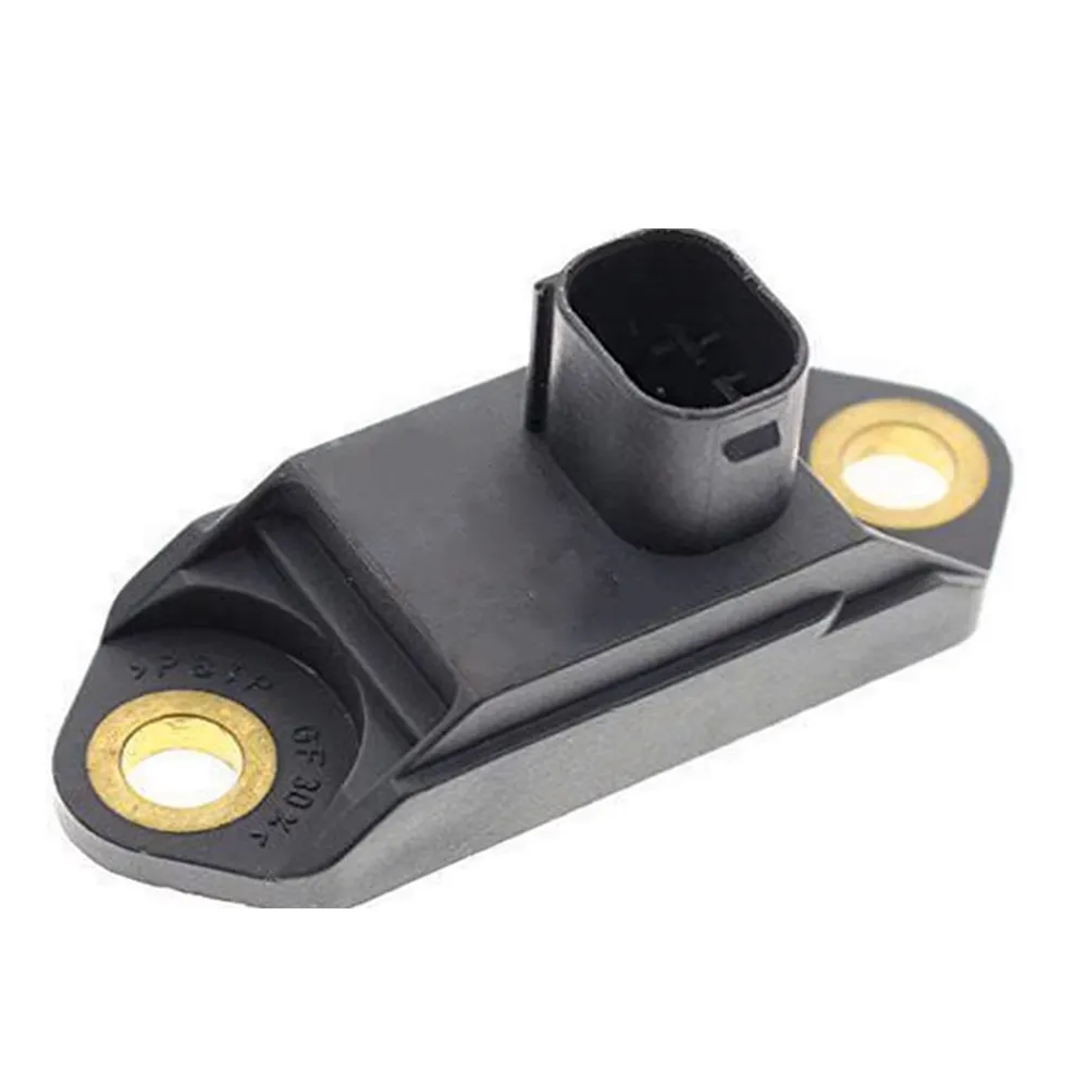
Connector and Mounting Choices
- Automotive-grade sealed connectors (e.g., TE, Molex, Yazaki) rated to –40°C to +125°C
- Custom mounting flanges to suit column or rack positions
- Optional anti-rotation brackets to prevent sensor drift over time
Design for Integration, Not Just Measurement
From a manufacturing engineer’s perspective, the best steering angle sensor is one that:
- Measures accurately and consistently
- Reports errors with confidence
- Interfaces easily with multiple platforms
- Meets global safety and EMC standards
When evaluating or sourcing these sensors, it’s essential to look beyond basic specs and into the signal integrity, diagnostic capability, and interface compatibility.
📚 Series Navigation
- Fundamentals of Automotive Steering Angle Sensors and Their Role in Vehicle Dynamics
- ✅ Design Architecture — Sensor Structure, Redundancy & Signal Interfaces
- Technical Specs that Matter — Resolution, Linearity, and Angular Range
- Environmental Testing & EMC Compliance in Real-World Applications
- Integration & Calibration on Vehicle Assembly Lines