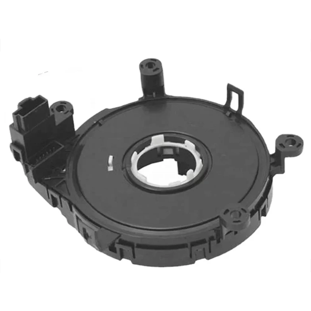
When assessing a steering angle sensor, it’s not just about whether it can detect rotation — it’s about how precisely, consistently, and predictably it can do so across all vehicle scenarios. As an engineer involved in sensor design and production, I always emphasize that resolution, linearity, angular range, and hysteresis are the real performance indicators that define whether a sensor is “fit for purpose” in EPS, ADAS, or autonomous platforms.
Resolution: Small Angles, Big Impact
دقة refers to the smallest measurable angle that the sensor can detect and output. In automotive applications, high resolution directly affects:
- EPS control smoothness
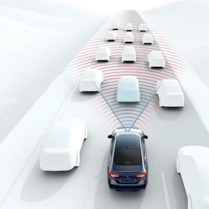
- Lane-centering accuracy in ADAS
- Parking maneuver precision
Typical industry values:
- 0.1° – 0.5°/bit for mid-range systems
- <0.05°/bit for premium or L3+ autonomy platforms
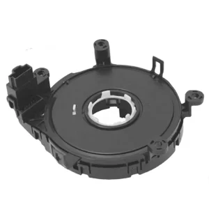
In Hall-effect sensors, resolution depends on:
- ال number of magnetic pole pairs
- ال ADC bit depth (often 12–16 bits)
- Interpolation algorithms in firmware
In real-world driving, a 1° resolution might feel “jumpy,” especially in fine control situations like automated parking or lane assist.
Linearity: Faithful Signal Mapping
Linearity error describes how closely the actual sensor output follows a perfectly proportional relationship to the rotation angle.
- Expressed as a percentage of full scale (±0.5%FS, for example)
- Non-linearity affects vehicle path prediction و steering torque modeling
Linearity may be degraded by:
- Mechanical misalignment
- Uneven magnetic fields
- Poor signal conditioning
To correct this, most SAS products use multi-point linearization algorithms stored in EEPROM during production calibration.
Angular Range: More Than One Turn
Many vehicles today demand sensors that can measure more than ±360° of rotation. Use cases include:
- Steering columns with lock-to-lock angles up to ±720° or ±900°
- Multi-turn EPS systems (rack-assist systems)
Two approaches to achieve this:
- Absolute multi-turn sensing with gear-linked optical/Hall encoders
- Software tracking of revolutions via direction and speed detection
The challenge is preserving absolute position after power loss. Premium systems may use energy-harvesting or battery-backed nonvolatile storage to retain angle.
Hysteresis: Eliminating Output Drift
Hysteresis refers to the difference in output between increasing and decreasing angles. In safety systems, this can lead to:
- Lagging response
- Inconsistent path estimation
- Oscillations in closed-loop control
A well-designed SAS should maintain hysteresis below ±0.2°, and ideally even tighter for ADAS systems.
Mitigation techniques include:
- Low-friction mechanical assemblies
- Stable temperature-compensated magnetics
- Precision ADC filtering
Temperature Drift and Thermal Compensation
Temperature variations from –40°C to +125°C can affect:
- Hall sensor output
- Magnetic field strength
- Mechanical expansion
To ensure reliability:
- Use N35/N48 grade magnets with stable thermal curves
- Embed onboard temperature sensors for real-time compensation
- Design for thermal soak scenarios (e.g., after prolonged sun exposure)
Factory Calibration and Zero-Point Accuracy
Each sensor must be calibrated for:
- Zero-point offset: Ensuring the “straight-ahead” position matches 0°
- Gain correction: Mapping full-scale rotation to output range
Two types of calibration:
- Fixed calibration at factory (e.g., with laser-aligned jigs)
- Field calibration during vehicle assembly or servicing
For systems requiring self-learning, the sensor must store the zero-point even after loss of power.
Why Specs Are Not Just Numbers
When specifying or selecting a steering angle sensor, resolution, linearity, and angular range define not only the raw performance but also the system stability in critical applications like ADAS and EPS.
From an engineering standpoint, these specs are inseparable from the sensor’s mechanical design, firmware intelligence، و integration strategy.
In short: Higher resolution without proper linearity is useless. Wide angle range without zero stability is dangerous. Choose wisely.