
Designing a reliable steering angle sensor (SAS) is only part of the journey. Once the sensor reaches the user, it must be precisely installed, electrically verified, Und calibrated in coordination with the vehicle’s steering and stability systems. As a manufacturing engineer, I’ve worked closely with vehicle integration teams to ensure SAS units not only perform in the lab—but operate flawlessly after final assembly. In this article, we explore how SAS is installed and zeroed, Die calibration workflows, and the diagnostics strategies used in mass production and service environments.
Installation: Mechanical Fit and Torque Control
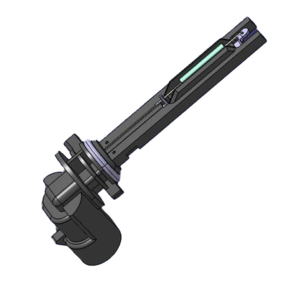
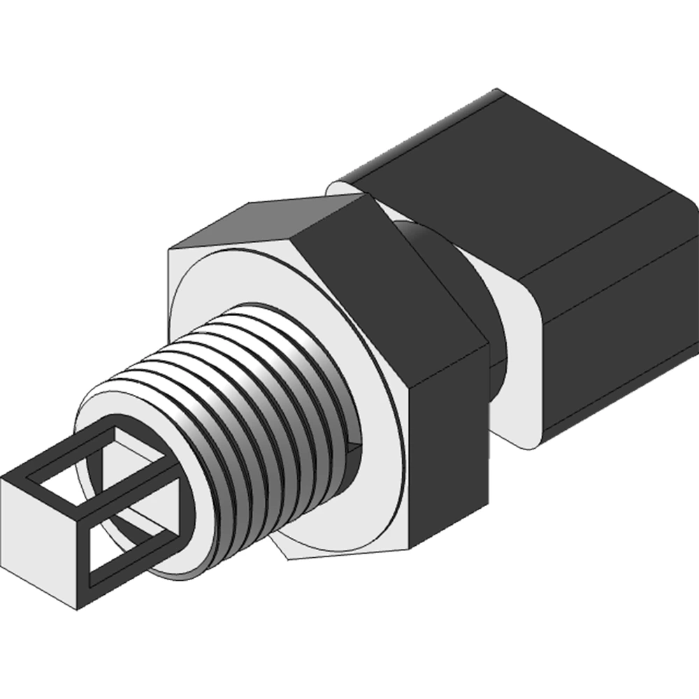
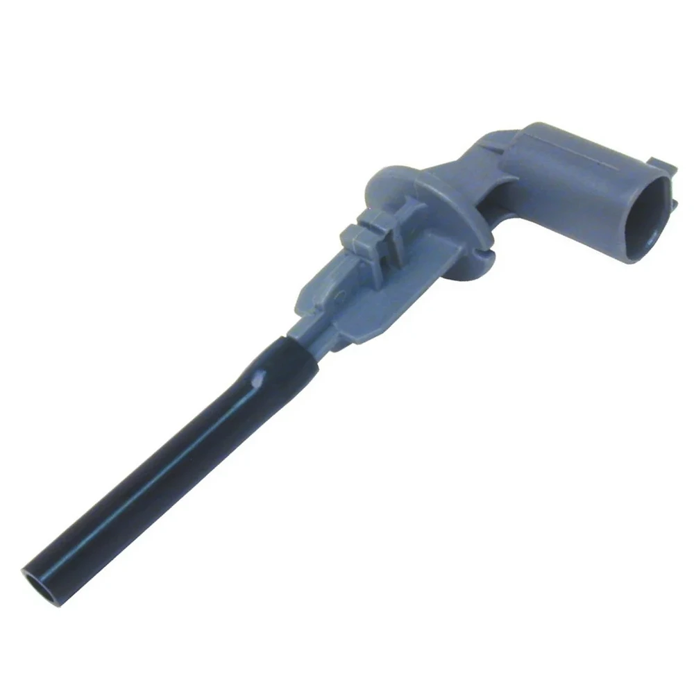
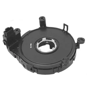
A steering angle sensor is typically mounted on:
- Der steering column shaft
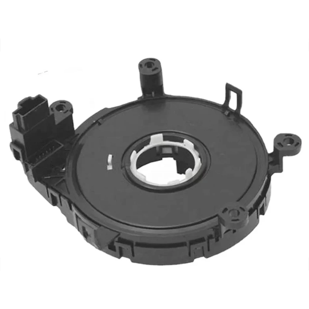
- Inside a clock spring assembly (for systems with integrated slip rings)
- Directly into electric power steering modules
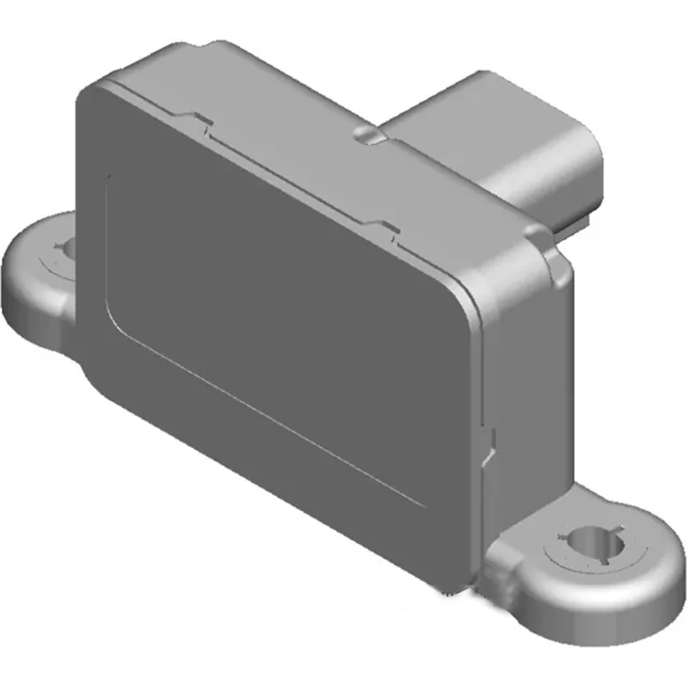
Key installation considerations:
- Alignment pin or slot to ensure angular positioning
- Mounting torque control (usually 0.6–1.2 Nm) to prevent deformation
- Avoid over-torque, which can stress plastic housings or shift magnetic alignment
Tip: Always verify that the steering wheel is centered and wheels are straight before tightening the sensor. Misalignment at this stage causes cascading calibration errors.
Electrical Connection and Protocol Matching
Modern SAS units support:
- CAN bus (11-bit or 29-bit ID, typically 250 or 500 kbps)
- LIN (used in simpler steering modules)
- Analog or PWM output (legacy or cost-sensitive designs)
During integration:
- The sensor must match the bus architecture and ID settings
- Connectors must provide low-resistance contact Und EMC shielding
- Pinouts must align with vehicle-side harnessing—miswiring can cause instant DTC (diagnostic trouble code)
Some SAS modules include redundant outputs (e.g., two angle signals) for functional safety (ISO 26262 ASIL-B or higher).
Zero-Point Calibration: The Most Critical Step
Zero-point calibration is the process of teaching the vehicle that the steering wheel is in the “straight-ahead” position.
Typical procedures:
- Mechanical centering of front wheels
- Sensor initialization via OEM tool (e.g., ODIS, GDS2, Techstream)
- Write-back of the 0° angle to sensor EEPROM
- CAN message confirmation with zero-angle flag set
Failing to calibrate correctly can lead to:
- ESP and ESC malfunction warnings
- Drifting steering assist
- Lane-keeping inaccuracy
Some OEMs integrate Selbstlernen logic that recalibrates zero-point over time, but initial alignment is still mandatory.
Diagnostics and Fault Detection
SAS units are required to support:
- Standardized DTC codes (e.g., U0126, C1231)
- Signal plausibility checking: sudden jumps or noisy output
- Angle out-of-range detection
- Voltage monitoring and watchdog resets
In mass production, diagnostic tools run a function test:
- Power supply check (9–16V)
- Angle signal response while rotating wheel
- CRC and firmware ID verification
Some SAS units offer UDS (Unified Diagnostic Services) over CAN for:
- Re-flashing firmware
- Resetting angle offset
- Reading out production date and calibration ID
Service and Recalibration Considerations
SAS recalibration is often needed:
- After steering rack or column replacement
- After alignment service
- When replacing clock spring or airbag module
To simplify this:
- Many sensors include non-volatile memory to retain last known angle
- Others feature auto-calibration logic triggered by driving patterns
From a service engineering perspective, fast and reliable recalibration means fewer returns and faster maintenance workflows.
Integration Is Where Theory Meets the Road
Even the most accurate SAS will underperform if poorly integrated. Mechanical alignment, communication setup, and calibration routines must be closely controlled during production and service workflows.
A successful SAS project doesn’t end with shipment—it ends with a car on the road, tracking straight, stable, and safe.
📚 Seriennavigation
- Grundlagen von Lenkwinkelsensoren in Kraftfahrzeugen und ihre Rolle in der Fahrzeugdynamik
- Designarchitektur – Sensorstruktur, Redundanz und Signalschnittstellen
- Wichtige technische Daten – Auflösung, Linearität und Winkelbereich
- Umweltprüfungen und EMV-Konformität in realen Anwendungen
- ✅ Integration und Kalibrierung an Fahrzeugmontagelinien