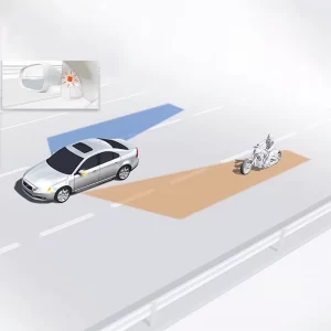
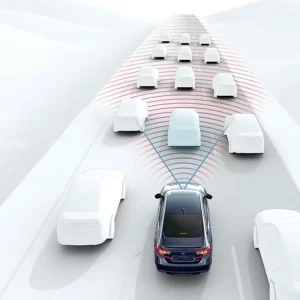
The true test of a steering angle sensor isn’t just how accurately it reads rotation—it’s how safely and reliably it delivers that signal under real-world automotive conditions. We consider the internal architecture, redundancy strategy, y interface selection to be just as important as performance specs. In this article, we’ll explore how steering angle sensors are structured for long-term durability and safety compliance, with a focus on signal interfaces and system integration.
Internal Architecture: A Dual-Channel Core
Most modern steering angle sensors employ a redundant dual-sensing architecture, typically using two Hall-effect sensor chips positioned 180° apart on the rotating shaft or magnet wheel.
Key reasons for redundancy:
- Fulfill ISO 26262 functional safety requirements (commonly ASIL-B or ASIL-C)
- Provide cross-checking for fault detection (e.g., stuck-at, drift, or dropout)
- Enable safe fallback modes in case of single-channel failure
In production, each sensing channel is tested independently, and the ECU constantly monitors for angle mismatch beyond an allowed deviation (e.g., 3°).
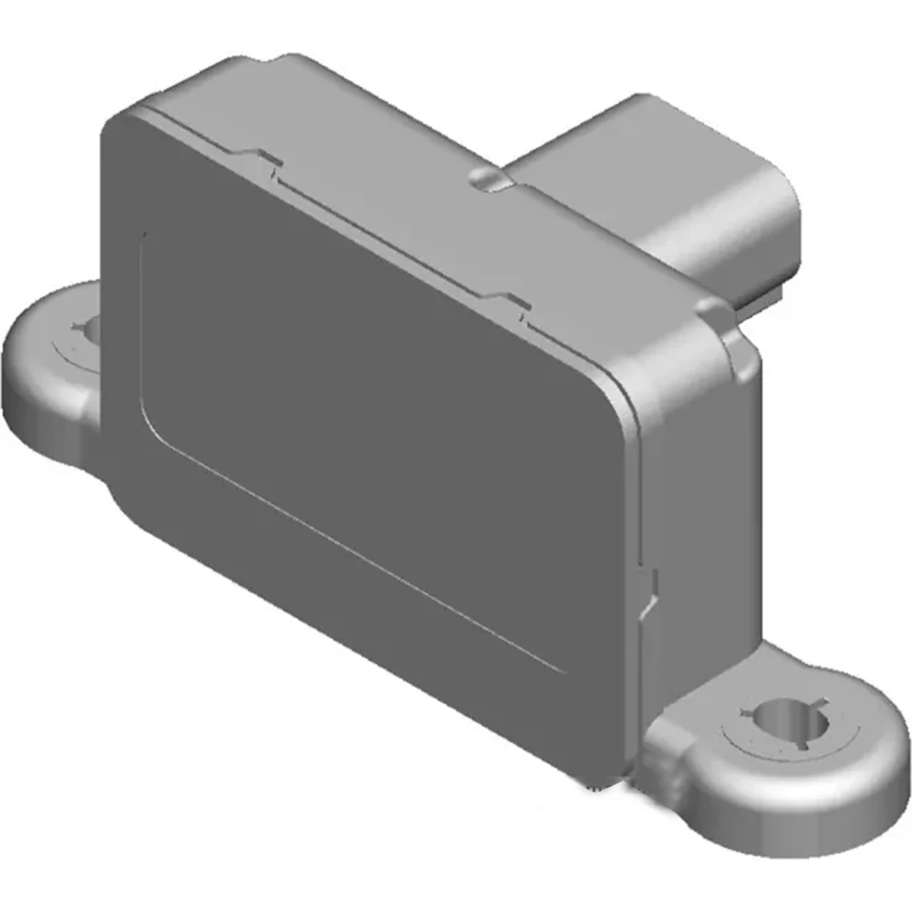
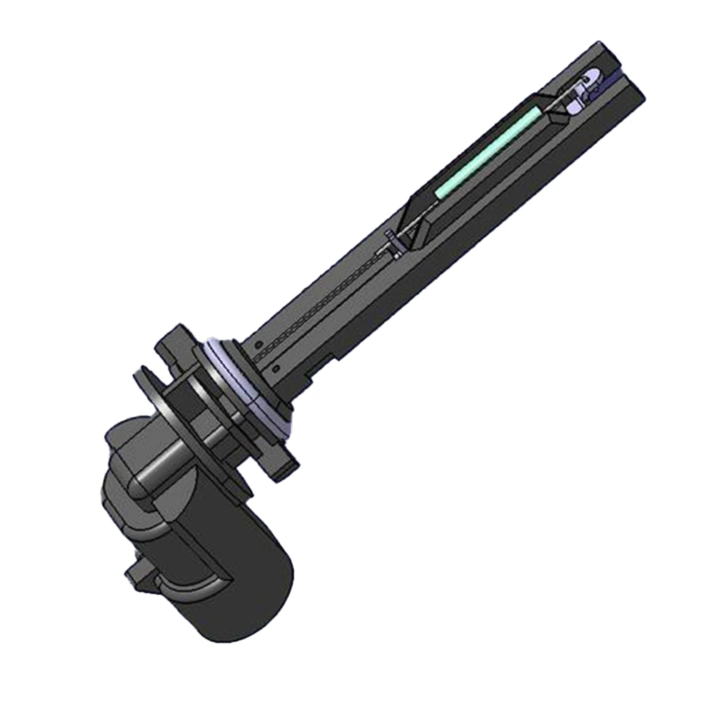
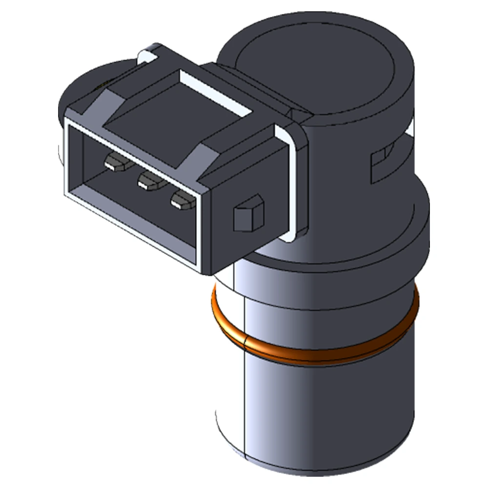
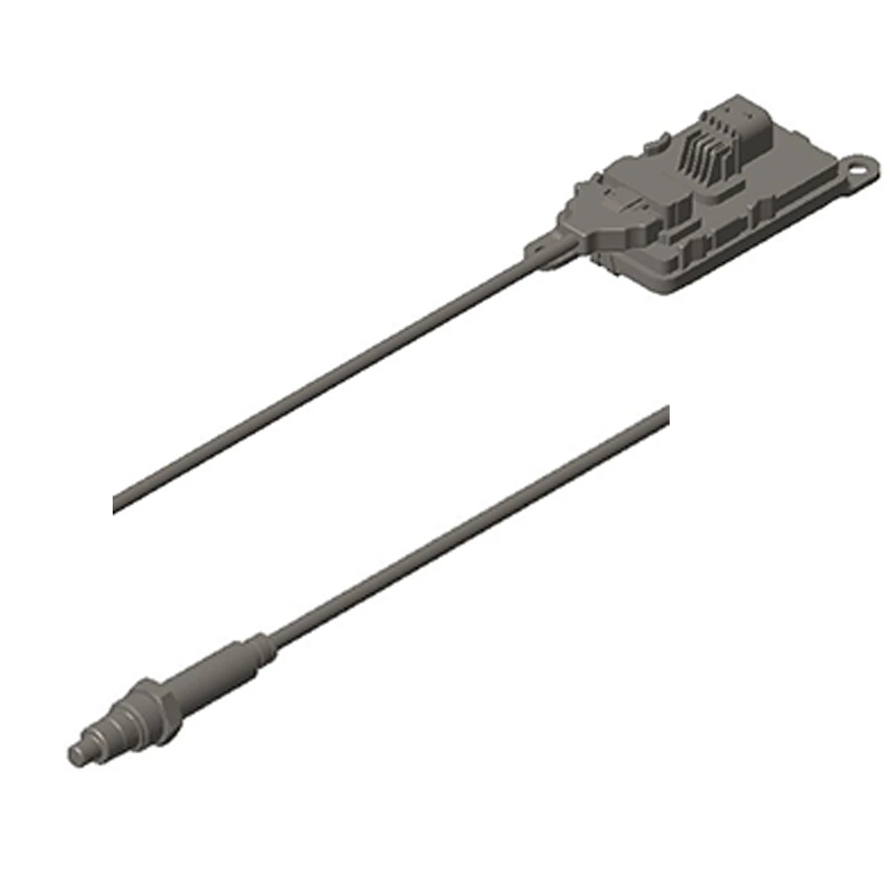
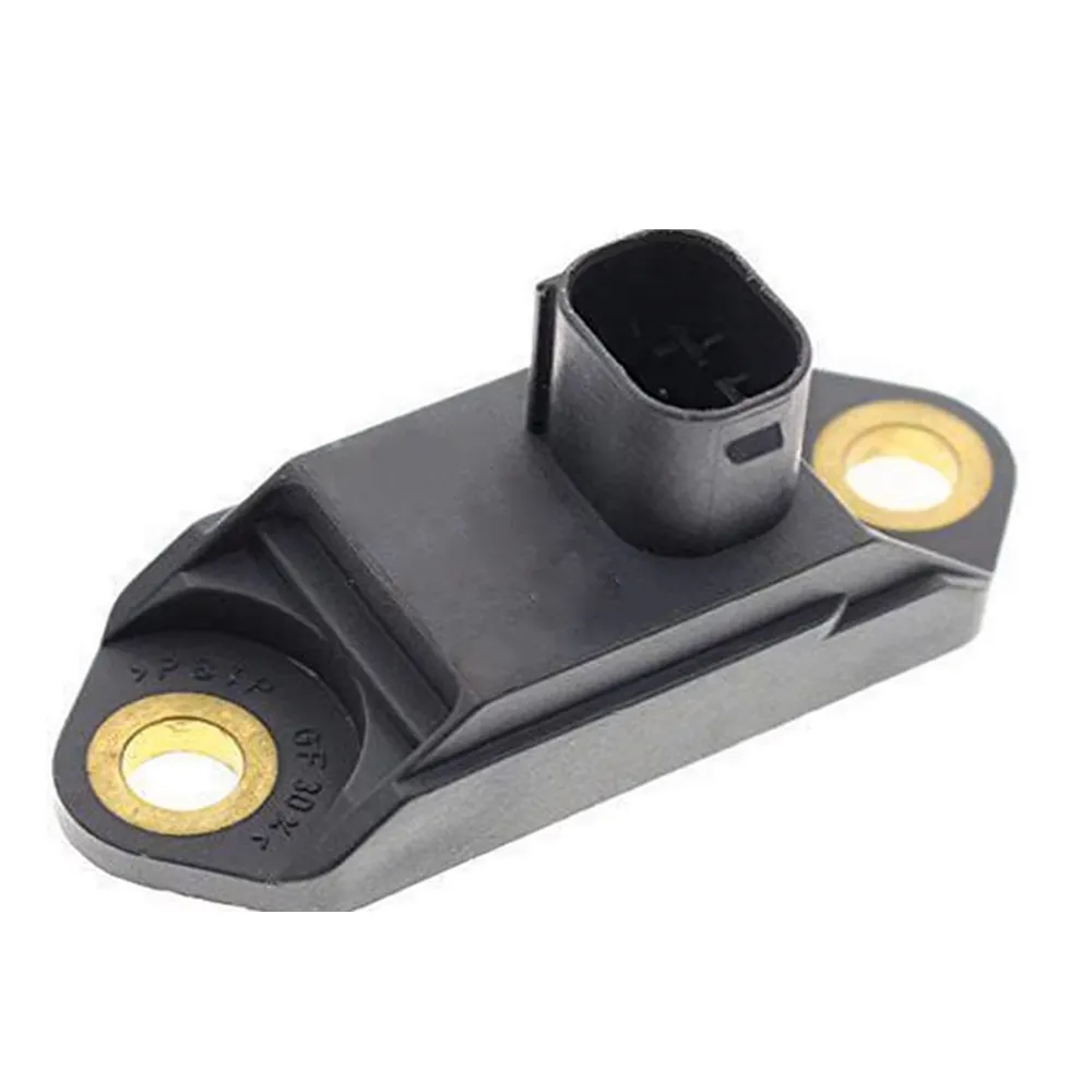
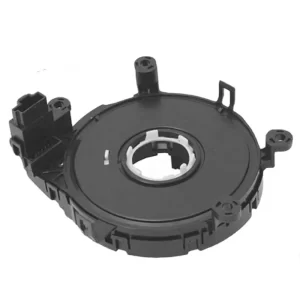
Mechanical Design: Rotational Assembly and Sealing
Sensor assemblies typically consist of:
- A multi-pole magnet ring or magnetized rotor
- One or two Hall-effect ICs
- A rigid PCB with redundant signal lines
- A sealed housing rated up to IP67/IP6K9K, especially for underhood installations
For angular measurements beyond 360° (e.g., ±720°), mechanical designs may include gear-driven rotary encoders or multi-turn tracking algorithms.
Signal Interfaces: From Analog to CAN and SENT
The signal output method has a direct impact on how the sensor integrates with other vehicle systems. Common interfaces include:
| Interface | Typical Use Case | Pros | Cons |
|---|---|---|---|
| Analog Voltage | Legacy or low-cost systems | Simple | Susceptible to EMI |
| PWM | Simple digital integration | Low-pin-count | Resolution limited by frequency |
| SENT | Entry-level digital, cost-effective | CRC-checked, fast | Needs decoding IC |
| SPI | Close-range, high-speed comm | Accurate | Requires shielded wiring |
| CAN | Advanced ADAS, EPS | Robust, standardized | Higher implementation cost |
Our team usually recommends SENT or CAN for applications where safety, speed, and fault tolerance are priorities.
Functional Safety Design: ISO 26262 Compliance
A critical part of modern sensor architecture is functional safety. Manufacturers are now expected to design in compliance with:
- ISO 26262 (Road Vehicles – Functional Safety)
- Diagnostic coverage (e.g., internal CRC, self-checks, power-on diagnostics)
- Dual-redundant signal paths and watchdog timers
- Design Failure Mode and Effects Analysis (DFMEA) procedures
Safety features built into the sensor firmware may include:
- Clamping outputs to fixed voltages under fault
- Signal de-correlation: Both channels send different waveforms that the ECU interprets
- Zero-point verification post ignition
Electrical and EMI Design Considerations
Steering angle sensors operate in environments with electrical noise from ignition coils, inverters, and LIN/CAN buses. Key protection design features include:
- TVS diodes for ESD protection
- Reverse polarity protection at the power input
- Shielded cables and twisted pair for CAN/SENT
- Robust ground isolation and filtering at the PCB level
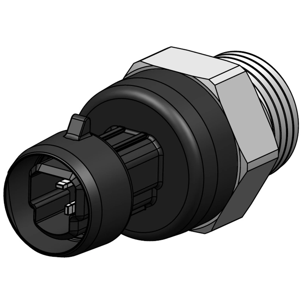
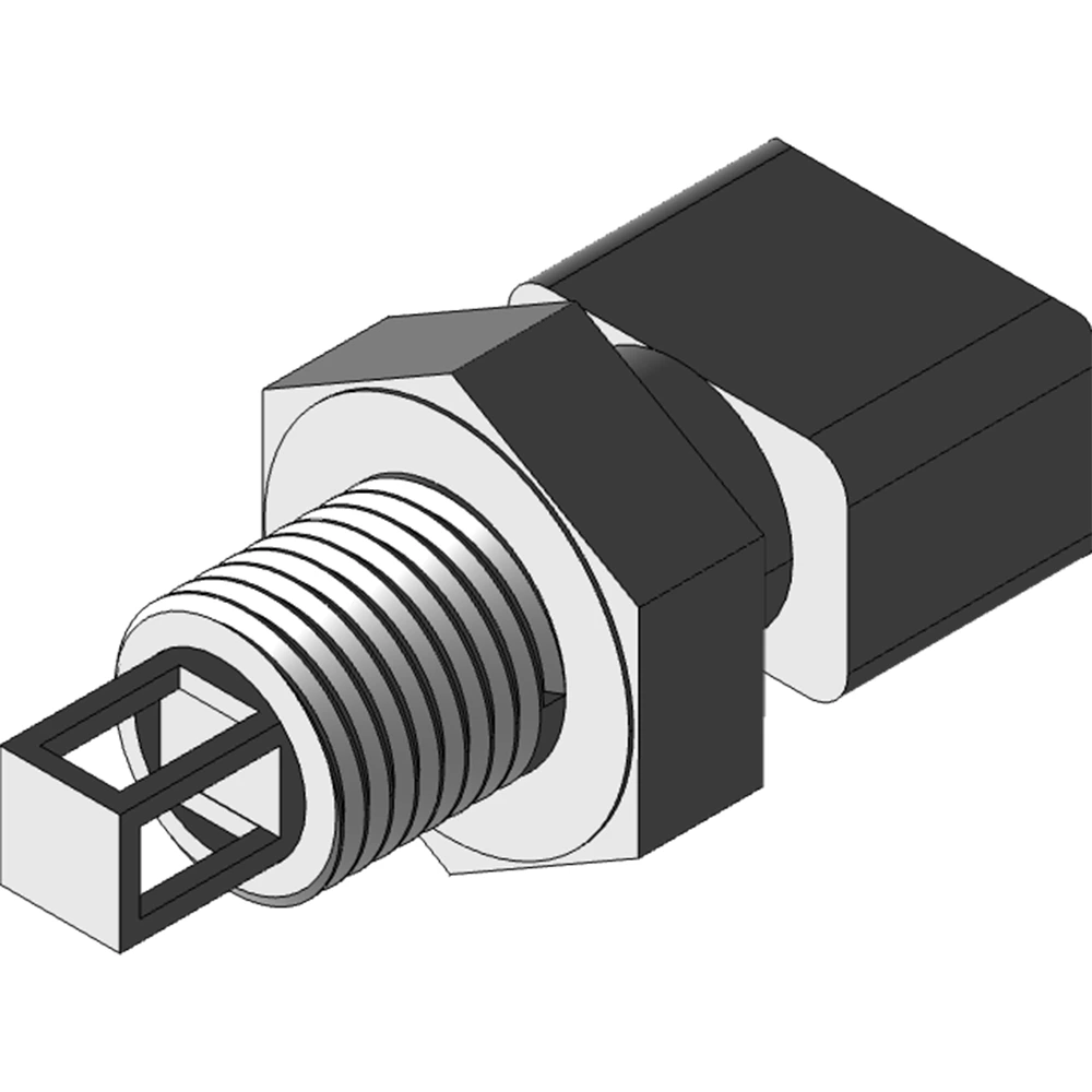
Connector and Mounting Choices
- Automotive-grade sealed connectors (e.g., TE, Molex, Yazaki) rated to –40°C to +125°C
- Custom mounting flanges to suit column or rack positions
- Optional anti-rotation brackets to prevent sensor drift over time
Design for Integration, Not Just Measurement
From a manufacturing engineer’s perspective, the best steering angle sensor is one that:
- Measures accurately and consistently
- Reports errors with confidence
- Interfaces easily with multiple platforms
- Meets global safety and EMC standards
When evaluating or sourcing these sensors, it’s essential to look beyond basic specs and into the signal integrity, diagnostic capability, y interface compatibility.
Navegación de la serie
- Fundamentos de los sensores de ángulo de dirección automotriz y su función en la dinámica del vehículo
- ✅ Arquitectura de diseño: estructura del sensor, redundancia e interfaces de señal
- Especificaciones técnicas importantes: resolución, linealidad y rango angular
- Pruebas ambientales y cumplimiento de EMC en aplicaciones del mundo real
- Integración y calibración en líneas de montaje de vehículos