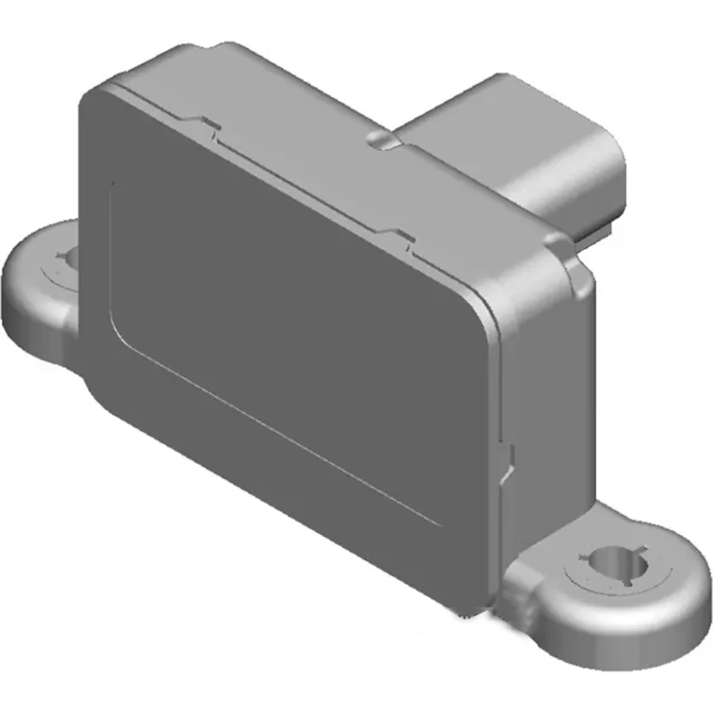
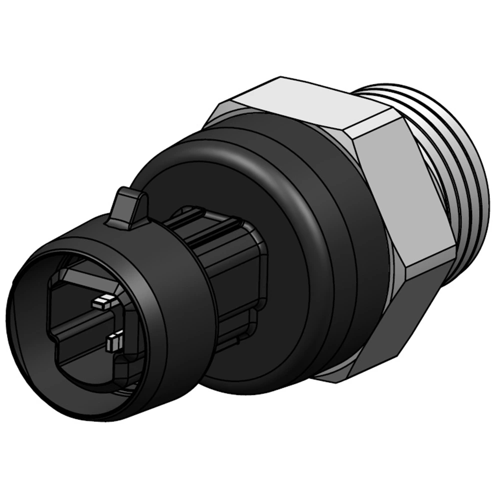
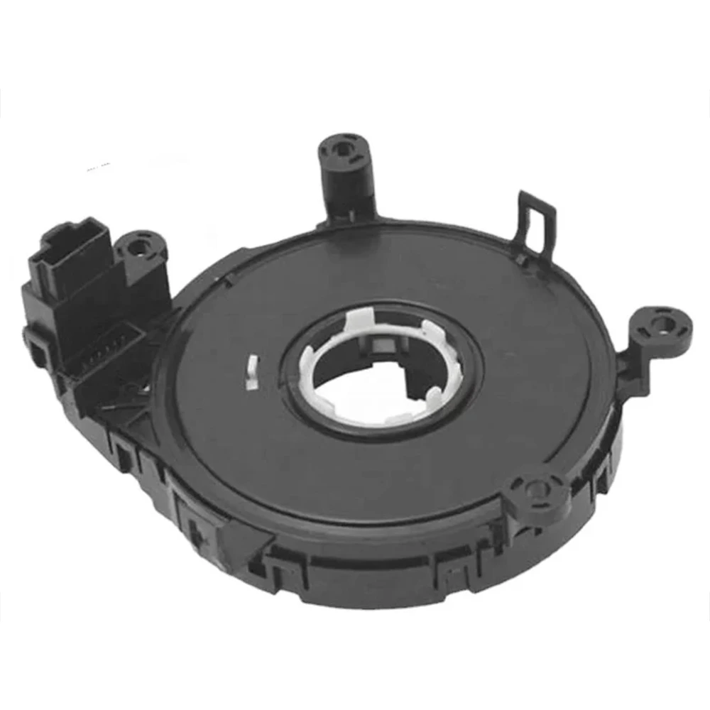
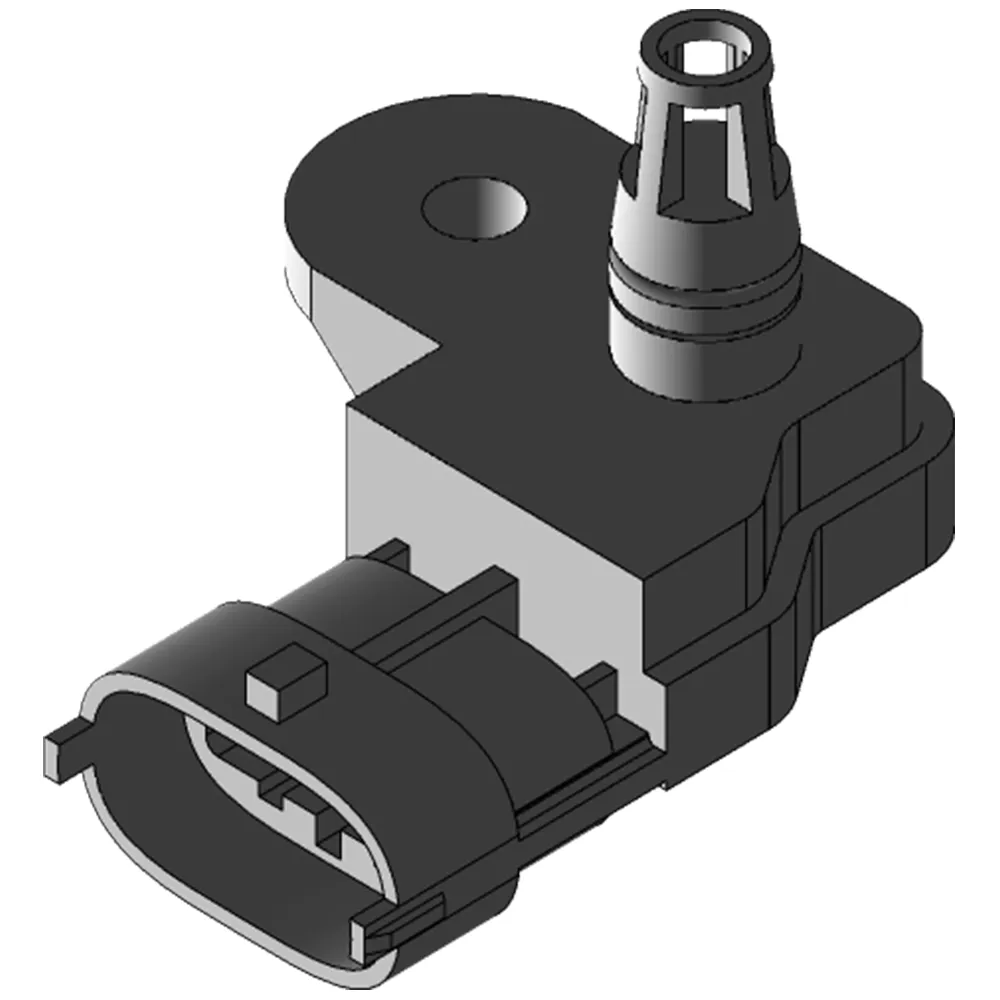
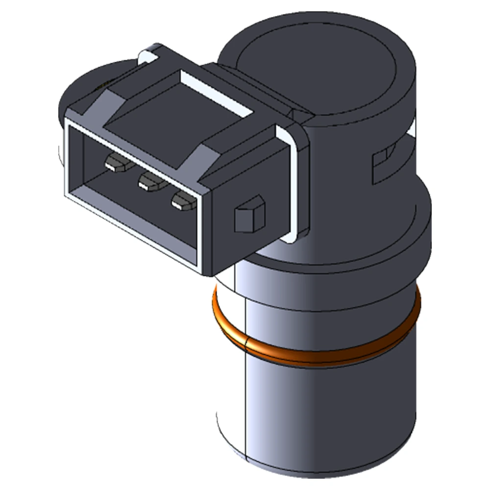
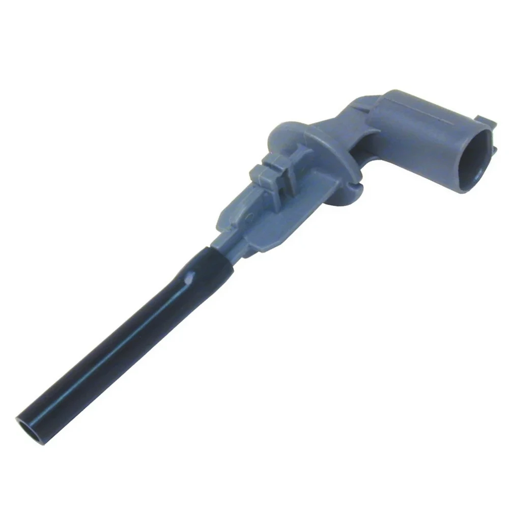
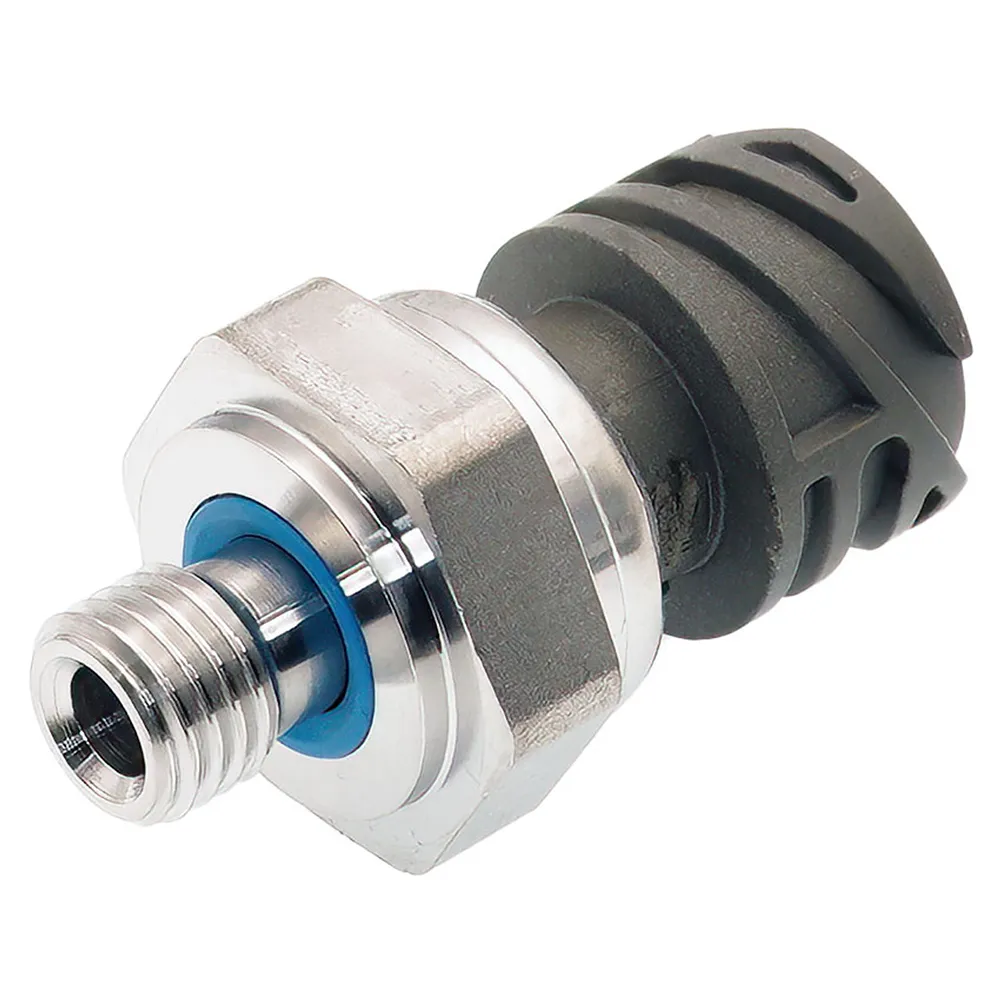
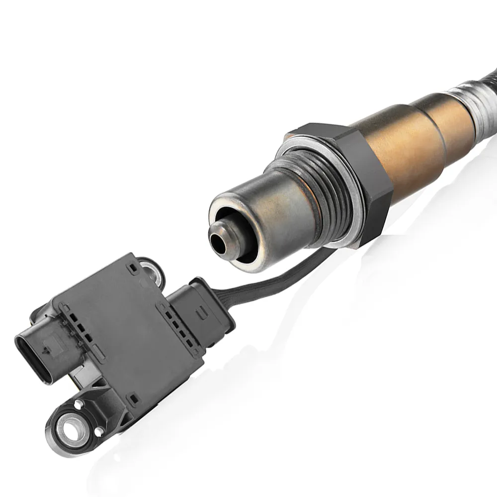
Ignition coils also have problems like other electronic components, such as sensors, EGR valves, turbochargers, etc. , so we need to learn how to troubleshoot problems, and it will be better if there are professionals.
To better know your ignition coil, you may would like to know:
- How does an ignition coil works?
- Why does an ignition coil failed?
- What is your ignition coil type?
- How to measure ignition coil?
We would like to demonstrate the diagnosis of a dual spark ignition coil with the following example “failure”.
Vehicle: Alfa Romeo 147 1.6 TS with twin spark ignition
Each cylinder has a master plug and a secondary plug. The ignition coils are started from the ignition power stages integrated in the engine control unit. Schematic illustrations, drawings and descriptions are intended only for explanations of the text of the document and cannot be used as a basis for installation and repair work.
Diagnostic work conditions: Engine mechanics, battery, starting system and fuel system OK.
PRACTICAL TIP
Before starting diagnostics, take into account the following factors:
- In order to allow correct allocation of the vehicle, it is important that the vehicle documents (registration documents) are included with the job sheet.
- Check the battery voltage. Insufficient voltage supply may cause system failure or result in incorrect measurements or voltage drops.
- Check the system-related fuses. A quick look in the fuse box might eliminate the first cause of the fault.
Customer complaint
- The customer has reported a functional problem with the engine control system
- Warning information on the instrument cluster:
Fault: Engine monitoring system.
Troubleshooting steps
1
Using the diagnostic unit
Connect the diagnostic tool to the 16-pin OBD connector. Depending on the vehicle manufacturer and registration date, a different diagnostic kit and additional adapter may be required. Perform the following applications on the diagnostic unit:
- Choose a program
- Choose a vehicle
- Select the fuel type
- Choose a model
- Select vehicle type
- Select the required function
- Select System: Depending on which diagnostic system is being used, additional safety instructions may be displayed here.
- Start error diagnostics
Adequate battery voltage and the correct connector are required to communicate with the electronic control unit. Insufficient supply voltage to the electronic control unit can be a sign of a defect in the wiring or a defect in the vehicle’s battery.
3
Evaluate the details
Learn more about possible causes of failures
- Ignition error
- Faulty injection valve
- Electronic control unit faulty
Note:If multiple error codes are displayed, clear the fault first. Once this is done, take a test drive connected to the diagnostic system. Monitor parameters and read error memory.
4
Determine the fault cause
Preparations for engine diagnostics
- Prepare the necessary additional diagnostic systems, such as a multimeter or oscilloscope.
- Finding technical documents
- Remove engine cover (if present)
5
Carry out a visual inspection
Before starting the actual diagnostic process, the engine wiring and plug connections should be checked for damage as much as possible. Kinks, lack of strain relief and “bites” in the wiring are all possible causes of this.
6
Check the primary actuation of the cylinder 3 ignition coil
- Remove the plug from the ignition coil
- Connect an oscilloscope or diagnostic tester to the measurement module
- Connect the ends of the probe PIN 1 and PIN 2 to the two-sided connector.
- Remove the plug connections from the injection valves.
- Starting the engine
The signal must be clearly detectable on the oscilloscope.
In this example, the measurement is successful.
7
Check voltage supply on the cylinder 3 ignition coil
- Remove the plug from the ignition coil.
- Measure the voltage at the two-way connector on the wiring side
- Connect the red cable of the multimeter to PIN 2 (+) and the black cable to the engine ground (-).
Turn on the ignition. A voltage above 10.5 V must be measured. Measured value: 11.93 V. Measurement OK.
8
Remove the ignition coil for further tests
- Remove the plug from the ignition coil
- Remove the high voltage cable of the second spark plug
- Remove the mounting screws
- Pull out the ignition coil vertically, keeping it parallel to the socket
To prevent damage to the spark plug connector,is important to prevent ignition coil rotation.
Tips:
Check the plug slot for soiling caused by oil and water penetration. Remove and check the spark plugs.
9
Measure the resistance
Use a multimeter to check the removed ignition coil. Connect an ohmmeter directly to the component connector PIN 1 and PIN 2 to measure the primary winding.
- Control value: 0.3 Ω – 1.0 Ω
- Actual value: 0.5 Ω (OK)
To measure the secondary winding, measure the probes directly high voltage outputs of the ignition coil.
- Control value: 8.0 kΩ – 15.0 kΩ
- Actual value: ∞ (break secondary coil)
In this context, please always observe the following vehicle manufacturer specifications.
Tips:
Vehicle ignition coils are identical and can be interchanged for testing.
10
Replace the ignition coil
Here, care must be taken that the spark plug connector and the high-voltage cable for the second plug fit properly. Attach the ignition coil using the fixing screws. Once this is done, insert all the plug connections for the ignition coil and the injection valve connectors.
Get Full Support
MOOCAR — as a leading exporter, we are continually developing breakthrough sensing and actuating solutions to help optimize emissions control, fuel economy, and drivability. In addition to the above parts, we offer full support of data, market information.

