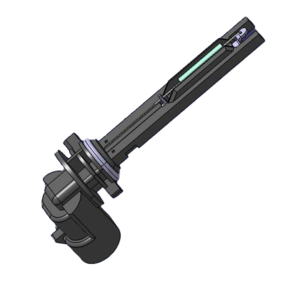

To design or select the right yaw rate sensor, it is essential to grasp its internal makeup and how each component works together to produce accurate angular velocity data. This article breaks down the MEMS gyro, signal conditioning stages, temperature compensation techniques, and enclosure design that form the heart of every automotive yaw rate sensor.
1. MEMS Vibrating Gyro Chip
- Working Principle
- Uses a MEMS vibrating proof-mass: when the vehicle rotates about the vertical axis, the Coriolis force causes tiny displacements in the vibrating structure
- Differential electrodes detect this displacement and convert it to an analog voltage signal
- Positive/negative voltage polarity corresponds to clockwise/counterclockwise yaw direction; downstream circuitry or MCU processes this signal into angular velocity
- Popular MEMS Chip Models
- Bosch BMI270: Integrates a low-noise gyro and 3-axis accelerometer; compact footprint and stable performance
- InvenSense ICM-42688-P: Ultra-low noise (~0.005°/s/√Hz), built-in temperature compensation
- STMicroelectronics L3GD20H: Common in industrial and automotive applications, fast response, supports SPI/I²C interfaces
- In-House or Custom Designs
- Some high-end OEMs partner with MEMS foundries to customize resonance cavity shapes for improved sensitivity and temperature drift
- Extreme test vehicles (±400°/s–±500°/s) may use specialized high-range MEMS or add circuit-level scaling to expand full-scale range
2. Analog Front End (AFE) & Signal Conditioning
- Front-End Amplification
- MEMS output is weak; a low-noise operational amplifier is used for first-stage or second-stage gain
- Amplification factor is chosen based on MEMS sensitivity (mV/°/s) and target ADC input range
- Hardware Filtering
- Commonly an LC filter or RC low-pass filter is placed after the amplifier to remove high-frequency EMI and mechanical vibration noise
- Cut-off frequency is typically set to 70 Hz or 100 Hz to balance response speed with noise rejection
- ADC & MCU Processing
- The filtered, amplified signal is fed into a 12-bit to 16-bit high-precision ADC for digitization
- An onboard MCU (e.g., STM32 series, NXP S32K series, TI TMS320 DSP) reads the digitized data, applies temperature compensation, additional digital filtering, and finally linearization
3. Temperature Sensing & Compensation
- Types of Temperature Sensors
- Internal Temperature Sensor: Most MEMS gyros include an embedded temperature sensor for real-time junction temperature measurement
- External Temperature Sensor: A separate NTC thermistor or digital temperature IC (e.g., TMP117) may be placed on the PCB to improve compensation accuracy
- Compensation Techniques
- Look-Up Table (LUT) Method: Factory calibration records zero bias and sensitivity at specific temperature points (–40 °C, –20 °C, 0 °C, 25 °C, 50 °C, 85 °C, 125 °C). The MCU interpolates between points in real time.
- Polynomial Curve Fitting: First- or second-order polynomial models fit bias and sensitivity drift vs. temperature, reducing memory footprint compared to LUTs
- Calibration Process
- Before mass production, each sensor is calibrated in a temperature chamber at the seven reference points. Zero bias and sensitivity coefficients are stored in MCU Flash.
- An automated flashing station writes compensation parameters to each unit and generates a traceable calibration label or report
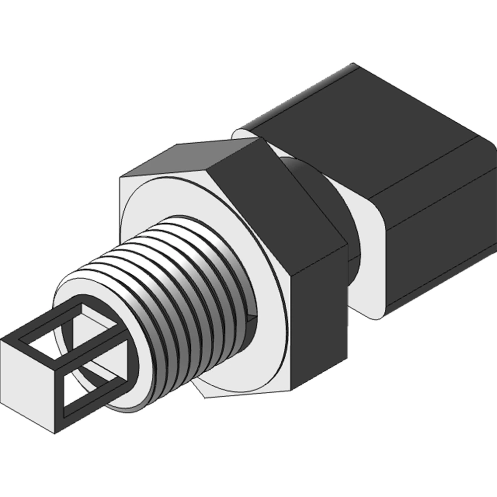
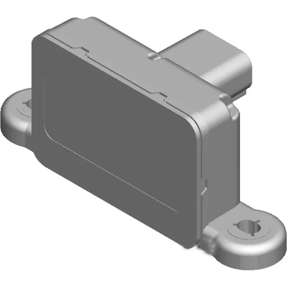
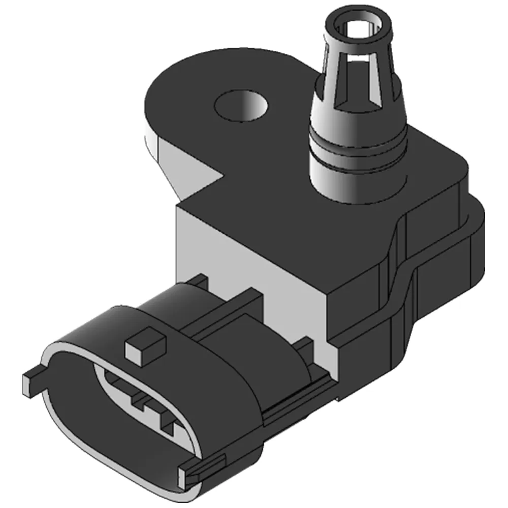
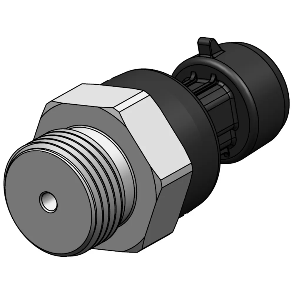
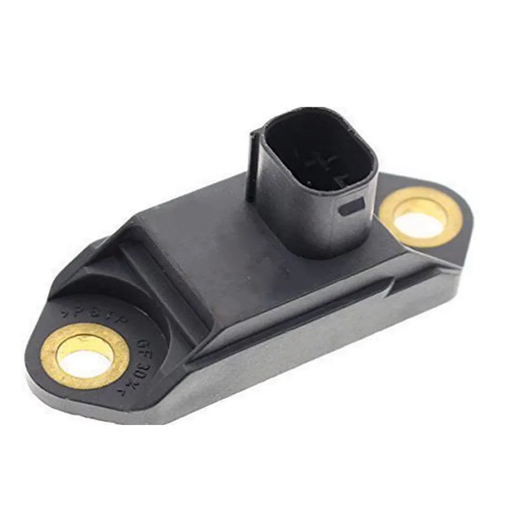
4. Enclosure & EMI Mitigation
- Enclosure Materials & Structure
- Plastic + Glass-Fiber Reinforced (PA66+GF30): Lightweight, cost-effective, suitable for most passenger cars and SUVs
- Aluminum Alloy (ADC12/AlSi10Mg): Better heat dissipation and EMI shielding, often used in high-end passenger or commercial vehicles
- Internal Support & Vibration Damping
- A damping foam pad or silicone damper is placed between the MEMS chip and the PCB to absorb vibrations in the 20 Hz–2000 Hz range
- PCB is typically four-layer or six-layer: top layer for signals, bottom layer for ground, middle layers for power and additional shielding to minimize EMI
- Shielding & Grounding
- The interior of the enclosure is coated with conductive paint or plated to create a Faraday cage, isolating internal signals from external EMI (e.g., ignition coils, alternator noise)
- The enclosure’s ground is tied to the vehicle chassis ground to reduce ground-loop noise and maintain a stable reference
Serie Navigatie: