


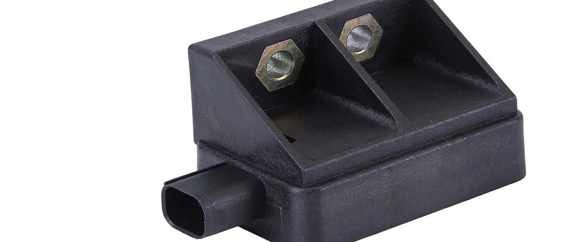
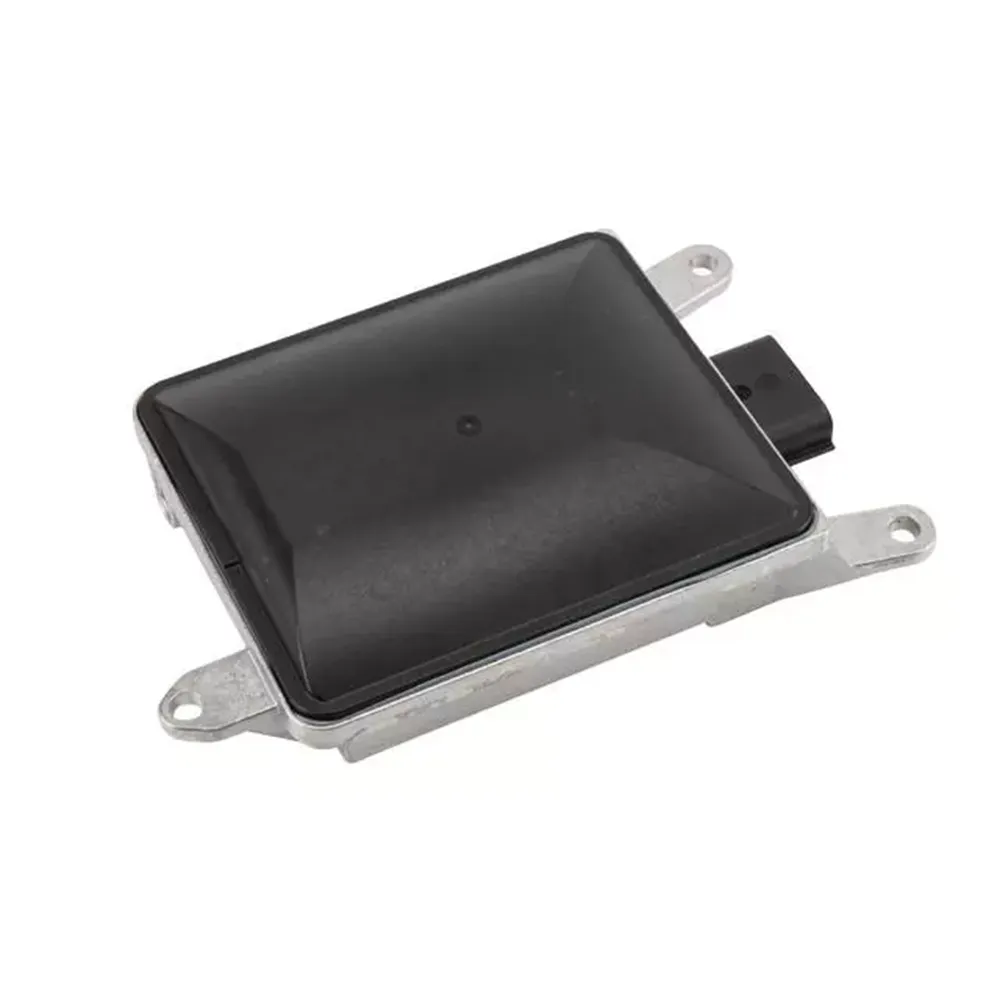
Step-by-Step Blind Spot Sensor Replacement Guide
Pre-Replacement Preparation
Critical Safety Precautions
- ⚠️ Disconnect battery (wait 15 min for capacitor discharge)
- 🧤 Wear ESD-safe gloves (sensors contain static-sensitive components)
- 🛑 Never force connectors (pins bend at 0.5N pressure)
- 📏 Prepare calibration space (5m × 15m clear area)
Tools & Materials
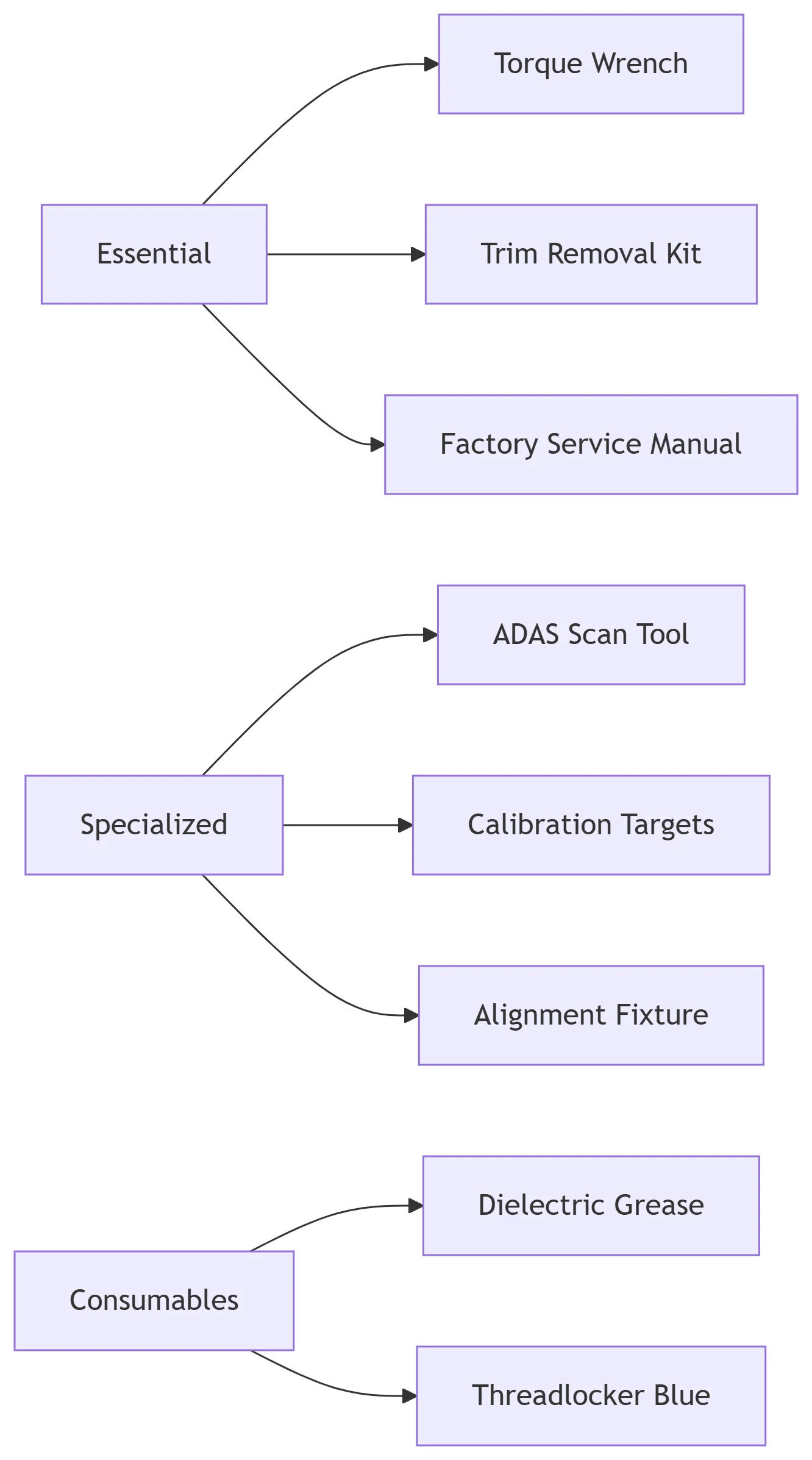
Pre-Installation Checklist
- Verify correct part number (cross-check VIN)
- Check sensor firmware version
- Inspect wiring harness for damage
- Clear DTCs before removal
Replacement Procedure (Sedan/SUV Example)
Step 1: Accessing the Sensor
- Remove rear wheel (for fender liner access)
- Detach interior trunk trim:
- Remove 8 plastic clips (press center pin first)
- Release 4 Christmas tree fasteners (twist 90°)
- Peel back sound deadening material
Step 2: Sensor Removal
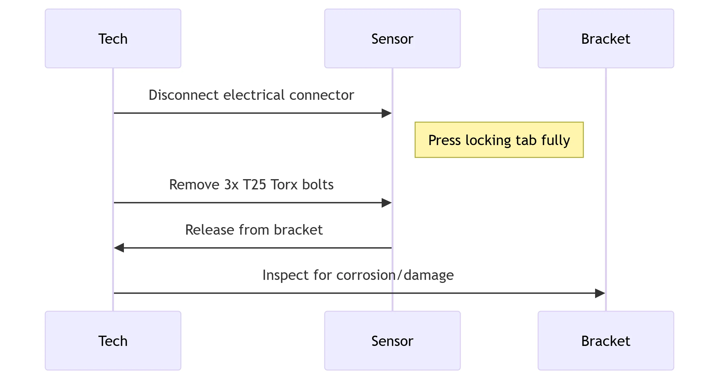
Critical Measurements:
- Bolt torque pattern: Star sequence
- Removal force: Never exceed 5N
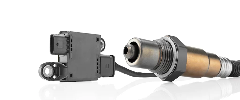
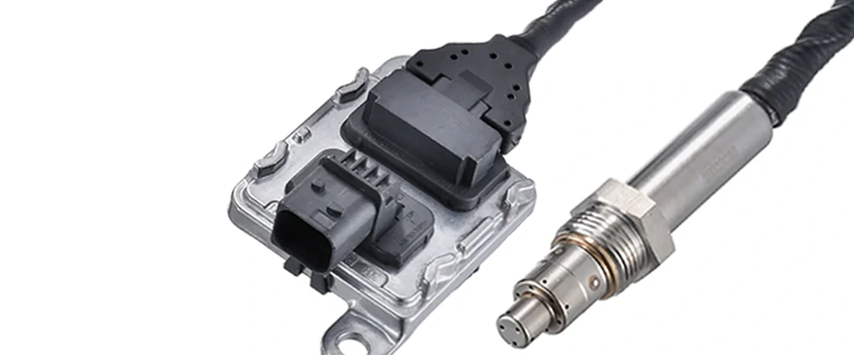
Step 3: New Sensor Installation
- Prep surfaces:
- Clean bracket with isopropyl alcohol
- Apply dielectric grease to connector
- Mounting procedure:
- Position sensor flush against bracket
- Hand-start all bolts
- Final torque: 2.4 Nm ± 0.2 (use inch-pound wrench)
- Connector engagement:
- Listen for audible click
- Tug test with 1kg force
Step 4: Reassembly
- Reverse removal steps
- Critical: Replace all one-time clips
- Apply threadlocker to bumper bolts
Calibration Procedures
Static Calibration (Workshop Method)
- Target Setup:
- Position reflective targets 2.5m from vehicle
- Align to manufacturer grid pattern
- Scan Tool Process:

- Tolerance Thresholds:
- Horizontal: ±0.3°
- Vertical: ±0.5°
- Distance: ±2cm
Dynamic Calibration (Road Test)
- Drive requirements:
- 15-minute continuous drive
- 64-80 km/h (40-50 mph)
- Straight highway preferred
- Verification:
- Scan tool: “Calibration Successful”
- Live data: Detection confidence >95%
Post-Installation Verification
Validation Tests
| Test Type | Procedure | Pass Criteria |
|---|---|---|
| Static | Bicycle target @ 5m | Detection within 1.2s |
| Dynamic | 30° approach @ 30km/h | Alert at 10±1m |
| Environmental | Light rain simulation | <5% false alerts |
Required Documentation
- Before/after calibration reports
- Replacement part certification
- Sensor alignment measurements
- System functionality sign-off
Common Installation Errors
| Mistake | Consequence | Prevention |
|---|---|---|
| Over-torquing | Radar field distortion | Use preset torque wrench |
| Connector mismatch | ECU damage | Verify pin-to-pin compatibility |
| Skipping calibration | System disablement | Pre-schedule calibration time |
| Wrong mounting angle | Blind zone gaps | Use laser alignment tool |
Professional Tips
- Thermal Management:
- Allow sensor to acclimate to ambient temperature
- Never install cold sensor on warm vehicle
- EMI Prevention:
- Route wires 15cm from high-voltage cables
- Add ferrite cores on power leads
- Software Best Practices:
- Flash latest firmware before installation
- Perform network reset after replacement
“I’ve replaced 300+ BSD sensors. The 3 golden rules? Torque precisely, calibrate religiously, and never assume pinouts match.”
- Carlos Mendoza, Audi Certified ADAS Tech
Warranty & Compliance
- OEM Requirements:
- Calibration certificate mandatory for warranty
- Use only approved diagnostic tools
- Legal Considerations:
- FMVSS 126 compliance verification
- Document all steps for liability protection
Series Navigation
- What is a Blind Spot Detection Sensor and Why It’s Critical for Road Safety
- How BSD Sensors Work with Lane Keep Assist and Cross-Traffic Alert
- Ruggedized BSD Solutions for Commercial Trucks and Heavy-Duty Vehicles
- Decoding Common BSD Sensor Fault Codes and Troubleshooting Steps
- Choosing the Right BSD System for Your Vehicle or Fleet
- Maintenance and Calibration of Blind Spot Detection Sensors
- Compact and Integrated BSD Designs for Modern EVs and Compact Cars
- Why BSD Sensors Fail: Causes, Warning Signs, and Prevention
- Step-by-Step Guide to Diagnosing BSD Sensor Issues
- ✅Replacing a Blind Spot Detection Sensor: Step-by-Step Instructions
- Common Pitfalls During BSD Sensor Replacement & How to Avoid Them

Related article resources and products

Ride Height Sensor
MOOCAR Ride Height Sensor monitors vehicle suspension levels to maintain optimal ride quality. MOOCAR Ride Height Sensor production processes comply with IATF16949 and ISO14001 standards,…

PDC Sensor
MOOCAR PDC Sensor delivers precise proximity detection to enhance parking safety. MOOCAR PDC Sensor production processes comply with IATF16949 and ISO14001 standards, with performance fully…
Cruise Control Distance Sensor
1. MOOCAR Cruise Control Distance Sensor ensures consistent vehicle spacing by accurately gauging distances. 2. MOOCAR Cruise Control Distance Sensor production processes comply with IATF16949…

DPF sensor – How it work & failed?
What is the DPF sensor?
How DPF sensor work?
Why DPF sensor failed?
What are ommon fault codes of DPF sensor?
What to pay attention to in the case…
What is an Adaptive Cruise Control (ACC) Distance Sensor and Its Role in Autonomous Driving
Discover how ACC distance sensors (radar/lidar/camera) enable self-driving capabilities. Learn their role in collision avoidance, traffic assist, and autonomous vehicle systems.
What Is Engine Management System (EMS) ?
Discover how your car’s Engine Management System (ECU) & sensors work together. Learn key components like O2, MAF, MAP sensors & their roles in performance,…