


Step-by-Step BSD Sensor Troubleshooting Guide
Safety Precautions
- ⚠️ Disconnect battery before handling wiring
- 🧤 Use ESD-safe gloves when handling sensors
- 🚫 Never probe live circuits without proper training
- 🔧 Secure vehicle on level surface with parking brake
Required Tools

Troubleshooting Flowchart

Step-by-Step Diagnostic Procedure
1️⃣ Preliminary Checks (5 Minutes)
- Visual Inspection
- Examine sensor for:
- Physical damage (cracks, dents)
- Moisture ingress (fogging inside lens)
- Obstructions (mud, snow, bumper stickers)
- Check mounting bracket security (should withstand 5N pull force)
- Verify connector seating (listen for click)
- Examine sensor for:
- Basic Function Test
- Drive at 30+ mph with helper vehicle in blind spot
- Verify warning indicators:
- Mirror light activation
- Steering wheel vibration (if equipped)
- Audible alert (if turn signal activated)
2️⃣ Electrical Diagnostics (15 Minutes)

- Power Supply Test
- Disconnect sensor
- Measure between pins 1 (+) and 2 (-):
- Ignition ON: 11-14V
- Engine running: 13.5-14.8V
- Acceptable voltage drop: <0.3V
- Ground Circuit Verification
- Measure resistance between:
- Sensor pin 2 and chassis ground
- Sensor pin 2 and battery negative
- Max resistance: 0.5Ω
- Measure resistance between:
- CAN Bus Integrity Check
- Measure voltage between:
- CAN High (pin 3) and ground: 2.5-3.5V
- CAN Low (pin 4) and ground: 1.5-2.5V
- Measure differential voltage: 1.8-2.2V
- Check termination resistance: 60Ω between CAN H/L
- Measure voltage between:
3️⃣ Advanced Diagnostics (20 Minutes)
Oscilloscope Tests
| Test | Normal Pattern | Fault Indicator |
|---|---|---|
| Power Stability | Flat line (ripple <100mV) | Spikes during engine start |
| CAN Signal | Clean square waves | Noise/distortion |
| Signal Integrity | Consistent pulse width | Dropouts during vibration |
- Vibration Stress Test
- Tap sensor housing while monitoring CAN signals
- Look for signal dropouts indicating cracked solder joints
- Temperature Stress Test
- Use thermal gun to heat sensor to 60°C
- Monitor for signal degradation
- Cool to -10°C with freeze spray
4️⃣ Real-World Diagnostic Scenarios
Case 1: Intermittent BSD Failure
Symptoms:
- Random system deactivation
- No consistent DTCs
Diagnosis:
- Found 3.2Ω resistance on ground circuit
- Traced to corroded splice under wheel arch
- Repair: Cut out corrosion, solder new connection
Case 2: False Alerts on Highway
Symptoms:
- BSD triggers with no vehicles present
- Worse in rain
Diagnosis:
- Water ingress in connector
- Salt corrosion on pins 3-4
- Repair: Clean with contact cleaner, apply dielectric grease
5️⃣ Post-Repair Validation
- Clear all DTCs
- Perform dynamic calibration:
- Drive 35-45 mph for 15 minutes on straight road
- Make 5-10 lane changes
- Verify system operation:
- Test with bicycle target (most sensitive)
- Test in rain (simulate with spray bottle)
- Test at dusk (sun angle interference)
Troubleshooting Reference Table
| Symptom | Most Likely Cause | Quick Test |
|---|---|---|
| No BSD activation | Power supply fault | Check fuse #32 |
| False alerts | Sensor obstruction | Clean with alcohol |
| Intermittent failure | Ground circuit issue | Voltage drop test |
| System disabled | CAN bus failure | Termination resistance |
| Alignment errors | Bracket damage | 8Nm torque check |
Pro Tips
- Always perform calibration after sensor removal
- For false alerts: Check for aftermarket accessories (bike racks, bull bars)
- In EVs: Test during regenerative braking (voltage spike issues)
- For fleet vehicles: Log failure times to identify pattern (e.g., failures after gravel roads)
“90% of ‘sensor failures’ are wiring or calibration issues. Never replace before verifying power, ground, and CAN integrity.”
- Martin Thorne, Master ADAS Technician
Series Navigation
- What is a Blind Spot Detection Sensor and Why It’s Critical for Road Safety
- How BSD Sensors Work with Lane Keep Assist and Cross-Traffic Alert
- Ruggedized BSD Solutions for Commercial Trucks and Heavy-Duty Vehicles
- Decoding Common BSD Sensor Fault Codes and Troubleshooting Steps
- Choosing the Right BSD System for Your Vehicle or Fleet
- Maintenance and Calibration of Blind Spot Detection Sensors
- Compact and Integrated BSD Designs for Modern EVs and Compact Cars
- Why BSD Sensors Fail: Causes, Warning Signs, and Prevention
- ✅Step-by-Step Guide to Diagnosing BSD Sensor Issues
- Replacing a Blind Spot Detection Sensor: Step-by-Step Instructions
- Common Pitfalls During BSD Sensor Replacement & How to Avoid Them

Related article resources and products
Exhaust Gas Pressure Sensor
MOOCAR Exhaust Gas Pressure Sensor accurately measures exhaust pressure to optimize engine performance. MOOCAR Exhaust Gas Pressure Sensor production processes comply with IATF16949 and ISO14001…
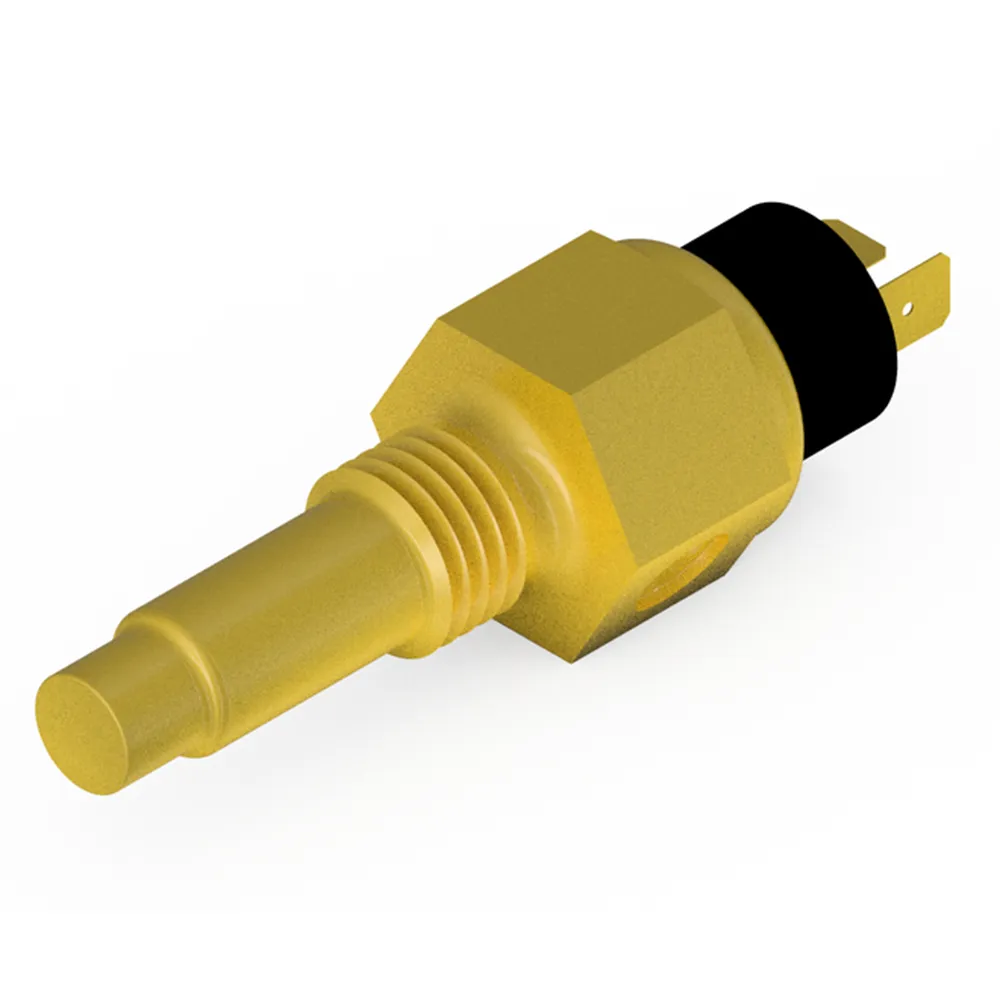
Coolant Temperature Sensor
MOOCAR Coolant Temperature Sensor provides real-time monitoring of engine temperature for optimal thermal management. MOOCAR Coolant Temperature Sensor production processes comply with IATF16949 and ISO14001…
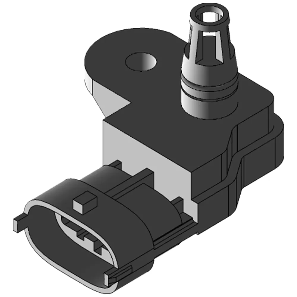
MAP Sensor
MOOCAR MAP Sensor measures manifold pressure for optimal engine tuning. MOOCAR MAP Sensor production processes comply with IATF16949 and ISO14001 standards, with performance fully aligned…

ACC Sensor Manufacturing & Calibration: Precision in the Cleanroom
Discover how ACC sensors are built! From cleanroom assembly to final calibration – learn the precision processes behind automotive radar manufacturing.
Crankshaft Position Sensor – How it works & failed?
How crankshaft position sensor works?
Why crankshaft position sensor failed?
What are common CKP sensor fault codes?
What are symptoms of CKP sensor malfunction?
How many CKP sensor types?
How…
Troubleshooting and Maintaining Blind Spot Detection Sensors: Maximizing Uptime & Safety
Extend BSD system life! Learn step-by-step diagnostics, cleaning protocols, calibration checks, and preventive maintenance for radar/camera-based blind spot sensors.