


Yaw Rate Sensor Interfaces
A yaw rate sensor’s usability depends on how well it connects, how easily it can be customized for different vehicle platforms, and how safely it arrives at its destination. This article examines common interface types (analog, CAN, LIN, SPI), best practices for installation, customization options, and recommended packaging and shipping methods to ensure smooth integration and delivery.
1. Interface Types & Pinouts
- Analog Voltage Output Version
- Pin Definitions
- VCC: +8 V to +16 V (typically +12 V)
- GND: Ground reference
- OUT: Analog voltage (0.5 V–4.5 V mapping to –FS–+FS)
- STATUS (optional): Fault/Ready status output (open-drain or push-pull)
- Usage Notes
- Load impedance should be between 1 kΩ and 10 kΩ to prevent voltage droop
- Keep harness lengths under 500 mm; if longer, increase wire gauge (≥AWG22) to reduce voltage drop
- Pin Definitions
- Digital CAN Output Version
- Pin Definitions
- VCC: +8 V to +16 V
- GND: Ground
- CAN_H / CAN_L: Differential CAN bus lines (up to 1 Mbps)
- WAKE (optional): Single-wire wake-up pin for standby modes
- STATUS (optional): Fault indicator or ready signal
- Usage Notes
- Requires 120 Ω termination resistor across CAN_H and CAN_L
- CAN ID, bitrate, and message timing (e.g., 10 ms or 20 ms cycle) can be factory-configured or reprogrammed via UDS
- Pin Definitions
- Digital LIN Output Version
- Pin Definitions
- VCC: +8 V to +16 V
- GND: Ground
- LIN: Single-wire LIN communication (typically 19.2 kbps)
- WAKE (optional): Wake-up via low/high on WAKE pin
- Usage Notes
- Requires external pull-up resistor (1 kΩ–2.2 kΩ) to +5 V on LIN line
- Node address (Slave ID) can be set at factory or via on-board programming
- Pin Definitions
- SPI/I²C Output Version (Development/Test)
- SPI Pins: SCLK (clock), MISO (master in/slave out), MOSI (master out/slave in), CS (chip select), VCC, GND
- I²C Pins: SCL (clock), SDA (data), VCC, GND
- Usage Notes
- SPI: Ensure clock polarity (CPOL) and phase (CPHA) match host settings; recommended clock ≤5 MHz
- I²C: Use pull-up resistors of 4.7 kΩ–10 kΩ; primarily for calibration and prototyping—mass-production often uses CAN/LIN
2. Installation Location & Mounting Tips
- Common Mounting Locations
- Under Steering Column: Close to vehicle center of gravity, minimizing chassis flex error
- Near Front Subframe: Preferred for commercial and heavy trucks due to closer proximity to vehicle mass center
- Behind Instrument Panel: Common for universal aftermarket modules, locking into a rigid substructure
- Alignment & Orientation
- Ensure sensor’s X/Y/Z axes align with vehicle’s coordinate system; otherwise, apply a 3D coordinate transformation in the ECU
- Mounting surface must be flat and free of gaps—avoid rubber isolation mounts that are too thick and introduce tilt
- Fastening Methods & Hardware
- Bolted: M4/M5 bolts with spring washers or nylon lock nuts to prevent loosening under vibration
- Snap-In Bracket: Allows quick removal but must guarantee bracket strength and precise alignment
- Temporary Epoxy/Silicone (Testing Only): Not recommended for production; use only on prototype vehicles
- Wiring Harness Routing
- Length: Keep harness under 500 mm; if longer, increase conductor gauge to prevent voltage drop, and add shielding if needed
- Shielding & Grounding: Surround CAN/LIN/analog wires with braided shield, tied to chassis ground at connector to resist EMI
- Avoid Heat & Sharp Edges: Route away from exhaust pipes, engine block hot spots, or interior sharp metal edges to prevent insulation wear
Series Navigation:
- Automotive Yaw Rate Sensor Positioning & Core Functions
- Yaw Rate Sensor Core Components & Working Principles
- Yaw Rate Sensor Technical Specifications & Model Guide
- Yaw Rate Sensor Environmental Adaptability & Reliability
- ✅Yaw Rate Sensor Interfaces
- Why Yaw Rate Sensors Fail: Root Causes, Warning Signs, and Repair Advice
- How to Troubleshoot Yaw Rate Sensors in Modern Vehicles
- How to Install a Yaw Rate Sensor: Step-by-Step Guide
- Common Mistakes in Yaw Rate Sensor Replacement

Related article resources and products
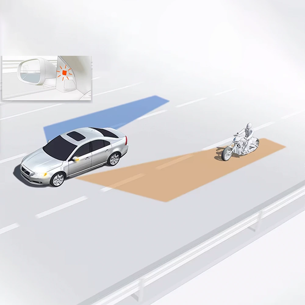
Blind Spot Detection Sensors
MOOCAR Blind Spot Detection Sensors deliver enhanced safety by accurately monitoring adjacent traffic. MOOCAR Blind Spot Detection Sensors production processes comply with IATF16949 and ISO14001…

Oil Temperature Sensor
MOOCAR Oil Temperature Sensor provides precise monitoring of oil temperature for optimal engine operation. MOOCAR Oil Temperature Sensor production processes comply with IATF16949 and ISO14001…
Exhaust Gas Pressure Sensor
MOOCAR Exhaust Gas Pressure Sensor accurately measures exhaust pressure to optimize engine performance. MOOCAR Exhaust Gas Pressure Sensor production processes comply with IATF16949 and ISO14001…

Performance Parameters of Automotive Longitudinal Acceleration Sensors — Accuracy, Bandwidth, and Drift
Discover the key performance metrics of longitudinal acceleration sensors, including measurement accuracy, bandwidth, linearity, noise density, and temperature drift in real-world automotive environments.
Fundamentals of Automotive Steering Angle Sensors and Their Role in Vehicle Dynamics
Discover how steering angle sensors work, their core technologies, and their critical role in systems like ESP, ADAS, and electric power steering. A guide from…
How to Install an Acceleration Sensor: Step-by-Step Guide
Learn how to correctly install a vehicle acceleration sensor (G-sensor) with this detailed guide. Includes mounting orientation, torque, calibration steps, and safety precautions.